EX6: Accessing Nios II memory mapped modules#
In this part we will look closer at how we from software can access and control a memory mapped module in the Nios II system.
The learning outcome of this problem is to:
Be able to write and read data from memory mapped peripherals.
Be able to use the PIO module to access external resources such as LEDs and switches.
For this purpose we can use the PIO (Parallel Input/Output) IP core. This core can provide general purpose input and output (GPIO) access to peripherals. These I/O ports can connect either to on-chip user logic, or to I/O pins that connect to devices external to the FPGA. For the example presented here we will use the PIO to acquire data from switches and to control LEDs, as shown in Fig. 35.
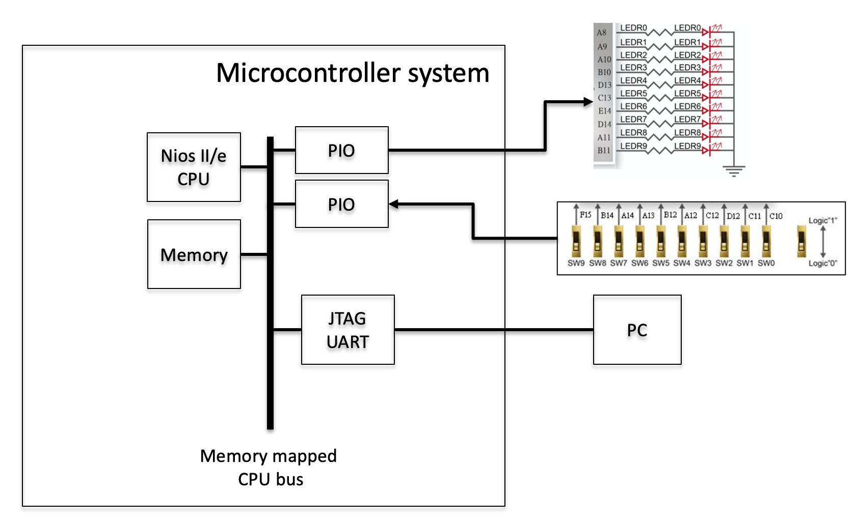
Fig. 35 Simplified overview of a basic Nios II system with PIO cores.#
The PIO module can also be used to assert an interrupt to the CPU based on input signals. This will be explored and demonstrated in Section 3.6.
Tip
More information on available IP cores can be found in the Intel Embedded Peripherals IP User Guide [Int21]. The PIO core is described in chapter 27 on page 307.
Example code on Github
The code for this example can be found here: fys4220/fys4220_nios2_example
Adding the PIO cores#
Open the nios2_system.qsys from EX5: A basic Nios II system in Platform Designer. From the IP catalog, add a PIO core.
Each PIO core can provide upt to 32 I/O ports which can be configured either as intput or output or both. In this example we will use two PIO cores, one with 10 inputs connected to the slide switches, and one with 10 ouputs connected to the LEDs. Name the two PIOs pio_sw and pio_led. Configure the widht of the two PIOs to be 10 bits, and set the direction according to each PIO core’s operation. See example in Fig. 36.
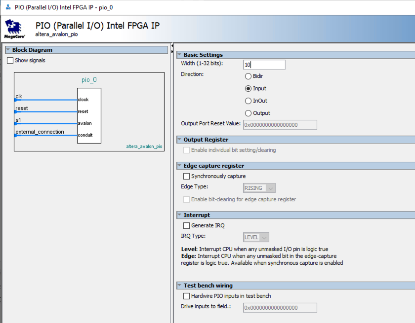
Fig. 36 Example for PIO core configures as a 10 bit wide input.#
Complete the both components interface connections, connecting to them to data interface of the CPU and to the clock and reset interface of the clock source.
Since the PIO components will be used to connect to FPGA hardware outside of the Nios-II system, the external connection interface has to be exported correctly. This can be done by double clicking the corresponding location in the Export column. Keep the default suggested names of led_pio_external_connection and sw_pio_external_connection.
Remember to remove and errors related to overlapping addresses by automatically assigned the base address for the newly integrated PIO cores (System–>Assign Base Address). The system should now look similar to Fig. 37.
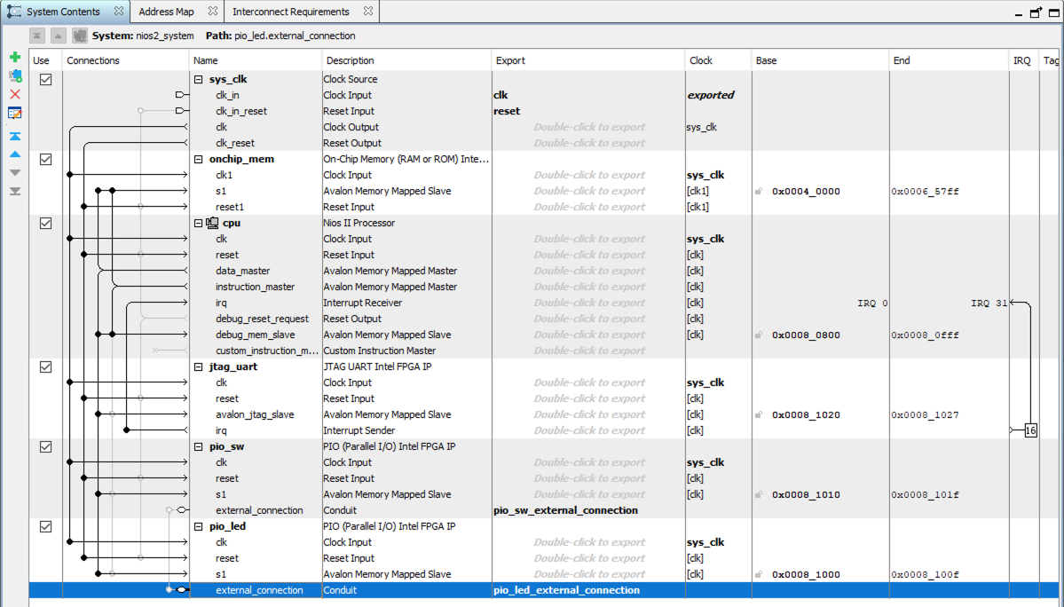
Fig. 37 Nios II system with PIO cores.#
Save and regenerated the HDL description of the system. This will update the HDL files found in the nios2_system folder as well as the nios2_system.sopc and nios2_system.qsys files.
Updating the top level HDL#
With the two PIO cores added to the system, it is necessary to also update the top level HDL description with the added external connections to the LEDs and switches. The updated instantiation template can be viewed from (Generate–>Show Instantiation Template). Or from the files nios2_system/nios2_system_inst.vhd. Add the additional ports and connect the top level ports to the respective ports on the Nios II system.
Remember to also add the relevant pin assignments for the LEDs and slide switches in the pinning assigment file. Run the updated Tcl-script to assign the pins.
Recompile the Quartus project to generate a new programming file with the updated system.
Updating the BSP#
Whenever the hardware description of the microcontroller system is modified, the corresponding board support package must also be updated to reflect these change. This can be done by regenerating the BSP project using the command demonstrated in Board Support Package. Navigate to the software folder and type:
$ nios2-bsp hal app_bsp ../quartus/nios2_system.sopcinfo
Nios II HAL macro#
To access a memory mapped module of the Nios II system, its low level interface needs to be specified as part of the hardware abstraction layer. A driver may not be provided for all modules, but as a minium all modules must have a header file that defines the the low level interface. Therefore, all modules support the hardware abstraction layer to some extent. If drivers are not available, the definitions in the header file must be used to access the hardware.
The most basic method to access a memory mapped module is through the HAL macros provided in the io.h header file of the BSP.
io.h
#ifndef __IO_H__
#define __IO_H__

/******************************************************************************
*                                                                             *
* License Agreement                                                           *
*                                                                             *
* Copyright (c) 2003 Altera Corporation, San Jose, California, USA.           *
* All rights reserved.                                                        *
*                                                                             *
* Permission is hereby granted, free of charge, to any person obtaining a     *
* copy of this software and associated documentation files (the "Software"),  *
* to deal in the Software without restriction, including without limitation   *
* the rights to use, copy, modify, merge, publish, distribute, sublicense,    *
* and/or sell copies of the Software, and to permit persons to whom the       *
* Software is furnished to do so, subject to the following conditions:        *
*                                                                             *
* The above copyright notice and this permission notice shall be included in  *
* all copies or substantial portions of the Software.                         *
*                                                                             *
* THE SOFTWARE IS PROVIDED "AS IS", WITHOUT WARRANTY OF ANY KIND, EXPRESS OR  *
* IMPLIED, INCLUDING BUT NOT LIMITED TO THE WARRANTIES OF MERCHANTABILITY,    *
* FITNESS FOR A PARTICULAR PURPOSE AND NONINFRINGEMENT. IN NO EVENT SHALL THE *
* AUTHORS OR COPYRIGHT HOLDERS BE LIABLE FOR ANY CLAIM, DAMAGES OR OTHER      *
* LIABILITY, WHETHER IN AN ACTION OF CONTRACT, TORT OR OTHERWISE, ARISING     *
* FROM, OUT OF OR IN CONNECTION WITH THE SOFTWARE OR THE USE OR OTHER         *
* DEALINGS IN THE SOFTWARE.                                                   *
*                                                                             *
* This agreement shall be governed in all respects by the laws of the State   *
* of California and by the laws of the United States of America.              *
*                                                                             *
* Altera does not recommend, suggest or require that this reference design    *
* file be used in conjunction or combination with any other product.          *
******************************************************************************/

/* IO Header file for Nios II Toolchain */

#include "alt_types.h"
#ifdef __cplusplus
extern "C"
{
#endif /* __cplusplus */

#ifndef SYSTEM_BUS_WIDTH
#define SYSTEM_BUS_WIDTH 32
#endif

/* Dynamic bus access functions */

#define __IO_CALC_ADDRESS_DYNAMIC(BASE, OFFSET) \
  ((void *)(((alt_u8*)BASE) + (OFFSET)))

#define IORD_32DIRECT(BASE, OFFSET) \
  __builtin_ldwio (__IO_CALC_ADDRESS_DYNAMIC ((BASE), (OFFSET)))
#define IORD_16DIRECT(BASE, OFFSET) \
  __builtin_ldhuio (__IO_CALC_ADDRESS_DYNAMIC ((BASE), (OFFSET)))
#define IORD_8DIRECT(BASE, OFFSET) \
  __builtin_ldbuio (__IO_CALC_ADDRESS_DYNAMIC ((BASE), (OFFSET)))

#define IOWR_32DIRECT(BASE, OFFSET, DATA) \
  __builtin_stwio (__IO_CALC_ADDRESS_DYNAMIC ((BASE), (OFFSET)), (DATA))
#define IOWR_16DIRECT(BASE, OFFSET, DATA) \
  __builtin_sthio (__IO_CALC_ADDRESS_DYNAMIC ((BASE), (OFFSET)), (DATA))
#define IOWR_8DIRECT(BASE, OFFSET, DATA) \
  __builtin_stbio (__IO_CALC_ADDRESS_DYNAMIC ((BASE), (OFFSET)), (DATA))

/* Native bus access functions */

#define __IO_CALC_ADDRESS_NATIVE(BASE, REGNUM) \
  ((void *)(((alt_u8*)BASE) + ((REGNUM) * (SYSTEM_BUS_WIDTH/8))))

#define IORD(BASE, REGNUM) \
  __builtin_ldwio (__IO_CALC_ADDRESS_NATIVE ((BASE), (REGNUM)))
#define IOWR(BASE, REGNUM, DATA) \
  __builtin_stwio (__IO_CALC_ADDRESS_NATIVE ((BASE), (REGNUM)), (DATA))

#ifdef __cplusplus
}
#endif

#endif /* __IO_H__ */
This file can be located in the HAL/inc folder of your BSP project and amongst others it provides the following macro functions. For more information about how to define macro objects and functions see section 7.3 in [BBM91].
IORD(BASE, OFFSET)
IOWR(BASE, OFFSET, DATA)
IORD: Returns data from forom a module with its memory mapped address at location BASE. The OFFSET specifies the relative register address within the module with respecte to the BASE address.
IOWR: Writes the value DATA to a module with its memory mapped address at location BASE. The OFFSET specifies the relative register address within the module with respecte to the BASE address.
The base address of a module is defined when building the Nios II system. To avoid hardcoding the address when using these macro functions, a macro object is generated by the software build tools that defines this address. The macro object is stored in the system.h file which can be found as part of the board support package project.
system.h
The system.h file for the example presented here, and found in the folder software/app_bsp
/*
 * system.h - SOPC Builder system and BSP software package information
 *
 * Machine generated for CPU 'cpu' in SOPC Builder design 'nios2_system'
 * SOPC Builder design path: ../../quartus/nios2_system.sopcinfo
 *
 * Generated: Mon Oct 11 14:35:33 CEST 2021
 */

/*
 * DO NOT MODIFY THIS FILE
 *
 * Changing this file will have subtle consequences
 * which will almost certainly lead to a nonfunctioning
 * system. If you do modify this file, be aware that your
 * changes will be overwritten and lost when this file
 * is generated again.
 *
 * DO NOT MODIFY THIS FILE
 */

/*
 * License Agreement
 *
 * Copyright (c) 2008
 * Altera Corporation, San Jose, California, USA.
 * All rights reserved.
 *
 * Permission is hereby granted, free of charge, to any person obtaining a
 * copy of this software and associated documentation files (the "Software"),
 * to deal in the Software without restriction, including without limitation
 * the rights to use, copy, modify, merge, publish, distribute, sublicense,
 * and/or sell copies of the Software, and to permit persons to whom the
 * Software is furnished to do so, subject to the following conditions:
 *
 * The above copyright notice and this permission notice shall be included in
 * all copies or substantial portions of the Software.
 *
 * THE SOFTWARE IS PROVIDED "AS IS", WITHOUT WARRANTY OF ANY KIND, EXPRESS OR
 * IMPLIED, INCLUDING BUT NOT LIMITED TO THE WARRANTIES OF MERCHANTABILITY,
 * FITNESS FOR A PARTICULAR PURPOSE AND NONINFRINGEMENT. IN NO EVENT SHALL THE
 * AUTHORS OR COPYRIGHT HOLDERS BE LIABLE FOR ANY CLAIM, DAMAGES OR OTHER
 * LIABILITY, WHETHER IN AN ACTION OF CONTRACT, TORT OR OTHERWISE, ARISING
 * FROM, OUT OF OR IN CONNECTION WITH THE SOFTWARE OR THE USE OR OTHER
 * DEALINGS IN THE SOFTWARE.
 *
 * This agreement shall be governed in all respects by the laws of the State
 * of California and by the laws of the United States of America.
 */

#ifndef __SYSTEM_H_
#define __SYSTEM_H_

/* Include definitions from linker script generator */
#include "linker.h"


/*
 * CPU configuration
 *
 */

#define ALT_CPU_ARCHITECTURE "altera_nios2_gen2"
#define ALT_CPU_BIG_ENDIAN 0
#define ALT_CPU_BREAK_ADDR 0x00080820
#define ALT_CPU_CPU_ARCH_NIOS2_R1
#define ALT_CPU_CPU_FREQ 50000000u
#define ALT_CPU_CPU_ID_SIZE 1
#define ALT_CPU_CPU_ID_VALUE 0x00000000
#define ALT_CPU_CPU_IMPLEMENTATION "tiny"
#define ALT_CPU_DATA_ADDR_WIDTH 0x14
#define ALT_CPU_DCACHE_LINE_SIZE 0
#define ALT_CPU_DCACHE_LINE_SIZE_LOG2 0
#define ALT_CPU_DCACHE_SIZE 0
#define ALT_CPU_EXCEPTION_ADDR 0x00040020
#define ALT_CPU_FLASH_ACCELERATOR_LINES 0
#define ALT_CPU_FLASH_ACCELERATOR_LINE_SIZE 0
#define ALT_CPU_FLUSHDA_SUPPORTED
#define ALT_CPU_FREQ 50000000
#define ALT_CPU_HARDWARE_DIVIDE_PRESENT 0
#define ALT_CPU_HARDWARE_MULTIPLY_PRESENT 0
#define ALT_CPU_HARDWARE_MULX_PRESENT 0
#define ALT_CPU_HAS_DEBUG_CORE 1
#define ALT_CPU_HAS_DEBUG_STUB
#define ALT_CPU_HAS_ILLEGAL_INSTRUCTION_EXCEPTION
#define ALT_CPU_HAS_JMPI_INSTRUCTION
#define ALT_CPU_ICACHE_LINE_SIZE 0
#define ALT_CPU_ICACHE_LINE_SIZE_LOG2 0
#define ALT_CPU_ICACHE_SIZE 0
#define ALT_CPU_INST_ADDR_WIDTH 0x14
#define ALT_CPU_NAME "cpu"
#define ALT_CPU_OCI_VERSION 1
#define ALT_CPU_RESET_ADDR 0x00040000


/*
 * CPU configuration (with legacy prefix - don't use these anymore)
 *
 */

#define NIOS2_BIG_ENDIAN 0
#define NIOS2_BREAK_ADDR 0x00080820
#define NIOS2_CPU_ARCH_NIOS2_R1
#define NIOS2_CPU_FREQ 50000000u
#define NIOS2_CPU_ID_SIZE 1
#define NIOS2_CPU_ID_VALUE 0x00000000
#define NIOS2_CPU_IMPLEMENTATION "tiny"
#define NIOS2_DATA_ADDR_WIDTH 0x14
#define NIOS2_DCACHE_LINE_SIZE 0
#define NIOS2_DCACHE_LINE_SIZE_LOG2 0
#define NIOS2_DCACHE_SIZE 0
#define NIOS2_EXCEPTION_ADDR 0x00040020
#define NIOS2_FLASH_ACCELERATOR_LINES 0
#define NIOS2_FLASH_ACCELERATOR_LINE_SIZE 0
#define NIOS2_FLUSHDA_SUPPORTED
#define NIOS2_HARDWARE_DIVIDE_PRESENT 0
#define NIOS2_HARDWARE_MULTIPLY_PRESENT 0
#define NIOS2_HARDWARE_MULX_PRESENT 0
#define NIOS2_HAS_DEBUG_CORE 1
#define NIOS2_HAS_DEBUG_STUB
#define NIOS2_HAS_ILLEGAL_INSTRUCTION_EXCEPTION
#define NIOS2_HAS_JMPI_INSTRUCTION
#define NIOS2_ICACHE_LINE_SIZE 0
#define NIOS2_ICACHE_LINE_SIZE_LOG2 0
#define NIOS2_ICACHE_SIZE 0
#define NIOS2_INST_ADDR_WIDTH 0x14
#define NIOS2_OCI_VERSION 1
#define NIOS2_RESET_ADDR 0x00040000


/*
 * Define for each module class mastered by the CPU
 *
 */

#define __ALTERA_AVALON_JTAG_UART
#define __ALTERA_AVALON_ONCHIP_MEMORY2
#define __ALTERA_AVALON_PIO
#define __ALTERA_NIOS2_GEN2


/*
 * System configuration
 *
 */

#define ALT_DEVICE_FAMILY "MAX 10"
#define ALT_ENHANCED_INTERRUPT_API_PRESENT
#define ALT_IRQ_BASE NULL
#define ALT_LOG_PORT "/dev/null"
#define ALT_LOG_PORT_BASE 0x0
#define ALT_LOG_PORT_DEV null
#define ALT_LOG_PORT_TYPE ""
#define ALT_NUM_EXTERNAL_INTERRUPT_CONTROLLERS 0
#define ALT_NUM_INTERNAL_INTERRUPT_CONTROLLERS 1
#define ALT_NUM_INTERRUPT_CONTROLLERS 1
#define ALT_STDERR "/dev/jtag_uart"
#define ALT_STDERR_BASE 0x81020
#define ALT_STDERR_DEV jtag_uart
#define ALT_STDERR_IS_JTAG_UART
#define ALT_STDERR_PRESENT
#define ALT_STDERR_TYPE "altera_avalon_jtag_uart"
#define ALT_STDIN "/dev/jtag_uart"
#define ALT_STDIN_BASE 0x81020
#define ALT_STDIN_DEV jtag_uart
#define ALT_STDIN_IS_JTAG_UART
#define ALT_STDIN_PRESENT
#define ALT_STDIN_TYPE "altera_avalon_jtag_uart"
#define ALT_STDOUT "/dev/jtag_uart"
#define ALT_STDOUT_BASE 0x81020
#define ALT_STDOUT_DEV jtag_uart
#define ALT_STDOUT_IS_JTAG_UART
#define ALT_STDOUT_PRESENT
#define ALT_STDOUT_TYPE "altera_avalon_jtag_uart"
#define ALT_SYSTEM_NAME "nios2_system"


/*
 * hal configuration
 *
 */

#define ALT_INCLUDE_INSTRUCTION_RELATED_EXCEPTION_API
#define ALT_MAX_FD 32
#define ALT_SYS_CLK none
#define ALT_TIMESTAMP_CLK none


/*
 * jtag_uart configuration
 *
 */

#define ALT_MODULE_CLASS_jtag_uart altera_avalon_jtag_uart
#define JTAG_UART_BASE 0x81020
#define JTAG_UART_IRQ 16
#define JTAG_UART_IRQ_INTERRUPT_CONTROLLER_ID 0
#define JTAG_UART_NAME "/dev/jtag_uart"
#define JTAG_UART_READ_DEPTH 64
#define JTAG_UART_READ_THRESHOLD 8
#define JTAG_UART_SPAN 8
#define JTAG_UART_TYPE "altera_avalon_jtag_uart"
#define JTAG_UART_WRITE_DEPTH 64
#define JTAG_UART_WRITE_THRESHOLD 8


/*
 * onchip_mem configuration
 *
 */

#define ALT_MODULE_CLASS_onchip_mem altera_avalon_onchip_memory2
#define ONCHIP_MEM_ALLOW_IN_SYSTEM_MEMORY_CONTENT_EDITOR 0
#define ONCHIP_MEM_ALLOW_MRAM_SIM_CONTENTS_ONLY_FILE 0
#define ONCHIP_MEM_BASE 0x40000
#define ONCHIP_MEM_CONTENTS_INFO ""
#define ONCHIP_MEM_DUAL_PORT 0
#define ONCHIP_MEM_GUI_RAM_BLOCK_TYPE "AUTO"
#define ONCHIP_MEM_INIT_CONTENTS_FILE "nios2_system_onchip_mem"
#define ONCHIP_MEM_INIT_MEM_CONTENT 0
#define ONCHIP_MEM_INSTANCE_ID "NONE"
#define ONCHIP_MEM_IRQ -1
#define ONCHIP_MEM_IRQ_INTERRUPT_CONTROLLER_ID -1
#define ONCHIP_MEM_NAME "/dev/onchip_mem"
#define ONCHIP_MEM_NON_DEFAULT_INIT_FILE_ENABLED 0
#define ONCHIP_MEM_RAM_BLOCK_TYPE "AUTO"
#define ONCHIP_MEM_READ_DURING_WRITE_MODE "DONT_CARE"
#define ONCHIP_MEM_SINGLE_CLOCK_OP 0
#define ONCHIP_MEM_SIZE_MULTIPLE 1
#define ONCHIP_MEM_SIZE_VALUE 153600
#define ONCHIP_MEM_SPAN 153600
#define ONCHIP_MEM_TYPE "altera_avalon_onchip_memory2"
#define ONCHIP_MEM_WRITABLE 1


/*
 * pio_led configuration
 *
 */

#define ALT_MODULE_CLASS_pio_led altera_avalon_pio
#define PIO_LED_BASE 0x81000
#define PIO_LED_BIT_CLEARING_EDGE_REGISTER 0
#define PIO_LED_BIT_MODIFYING_OUTPUT_REGISTER 0
#define PIO_LED_CAPTURE 0
#define PIO_LED_DATA_WIDTH 10
#define PIO_LED_DO_TEST_BENCH_WIRING 0
#define PIO_LED_DRIVEN_SIM_VALUE 0
#define PIO_LED_EDGE_TYPE "NONE"
#define PIO_LED_FREQ 50000000
#define PIO_LED_HAS_IN 0
#define PIO_LED_HAS_OUT 1
#define PIO_LED_HAS_TRI 0
#define PIO_LED_IRQ -1
#define PIO_LED_IRQ_INTERRUPT_CONTROLLER_ID -1
#define PIO_LED_IRQ_TYPE "NONE"
#define PIO_LED_NAME "/dev/pio_led"
#define PIO_LED_RESET_VALUE 0
#define PIO_LED_SPAN 16
#define PIO_LED_TYPE "altera_avalon_pio"


/*
 * pio_sw configuration
 *
 */

#define ALT_MODULE_CLASS_pio_sw altera_avalon_pio
#define PIO_SW_BASE 0x81010
#define PIO_SW_BIT_CLEARING_EDGE_REGISTER 0
#define PIO_SW_BIT_MODIFYING_OUTPUT_REGISTER 0
#define PIO_SW_CAPTURE 0
#define PIO_SW_DATA_WIDTH 10
#define PIO_SW_DO_TEST_BENCH_WIRING 0
#define PIO_SW_DRIVEN_SIM_VALUE 0
#define PIO_SW_EDGE_TYPE "NONE"
#define PIO_SW_FREQ 50000000
#define PIO_SW_HAS_IN 1
#define PIO_SW_HAS_OUT 0
#define PIO_SW_HAS_TRI 0
#define PIO_SW_IRQ -1
#define PIO_SW_IRQ_INTERRUPT_CONTROLLER_ID -1
#define PIO_SW_IRQ_TYPE "NONE"
#define PIO_SW_NAME "/dev/pio_sw"
#define PIO_SW_RESET_VALUE 0
#define PIO_SW_SPAN 16
#define PIO_SW_TYPE "altera_avalon_pio"

#endif /* __SYSTEM_H_ */
This file also includes a number of other macro objects for each module of the system. An example of all the macros that are defined for a Nios II PIO module is shown below.
/*
 * pio_led configuration
 *
 */

#define ALT_MODULE_CLASS_pio_led altera_avalon_pio
#define PIO_LED_BASE 0x81000
#define PIO_LED_BIT_CLEARING_EDGE_REGISTER 0
#define PIO_LED_BIT_MODIFYING_OUTPUT_REGISTER 0
#define PIO_LED_CAPTURE 0
#define PIO_LED_DATA_WIDTH 10
#define PIO_LED_DO_TEST_BENCH_WIRING 0
#define PIO_LED_DRIVEN_SIM_VALUE 0
#define PIO_LED_EDGE_TYPE "NONE"
#define PIO_LED_FREQ 50000000
#define PIO_LED_HAS_IN 0
#define PIO_LED_HAS_OUT 1
#define PIO_LED_HAS_TRI 0
#define PIO_LED_IRQ -1
#define PIO_LED_IRQ_INTERRUPT_CONTROLLER_ID -1
#define PIO_LED_IRQ_TYPE "NONE"
#define PIO_LED_NAME "/dev/pio_led"
#define PIO_LED_RESET_VALUE 0
#define PIO_LED_SPAN 16
#define PIO_LED_TYPE "altera_avalon_pio"
This module is generated as part of the embedded systems project in this course and will be used to access the LEDs on the DE10-Lite board. For this example the base address is defined as PIO_LED_BASE replaces the need to use the hardcoded addres value of 0x81000. This address corresponds to the base address shown for the LED PIO module in Fig. 37.
If changes are made to a system the base addresses of the modules may change. As a consequence the system.h file will also be updated with the new address values. By using the defined macro object instead of the hardcoded address value, you therefore avoid having to also update your user application or driver code.
Important
The system.h file is automatically generated when generating the board support package and should NEVER be manually edited!
All modules connected to the Nios II system as part of the Avalon bus has a memory mapped register interface. The IOWR and IORD macros can be used to read from and write to these registers by providing the correct module or base address and internal register offset. The register map for the PIO module is shown in figure 52.
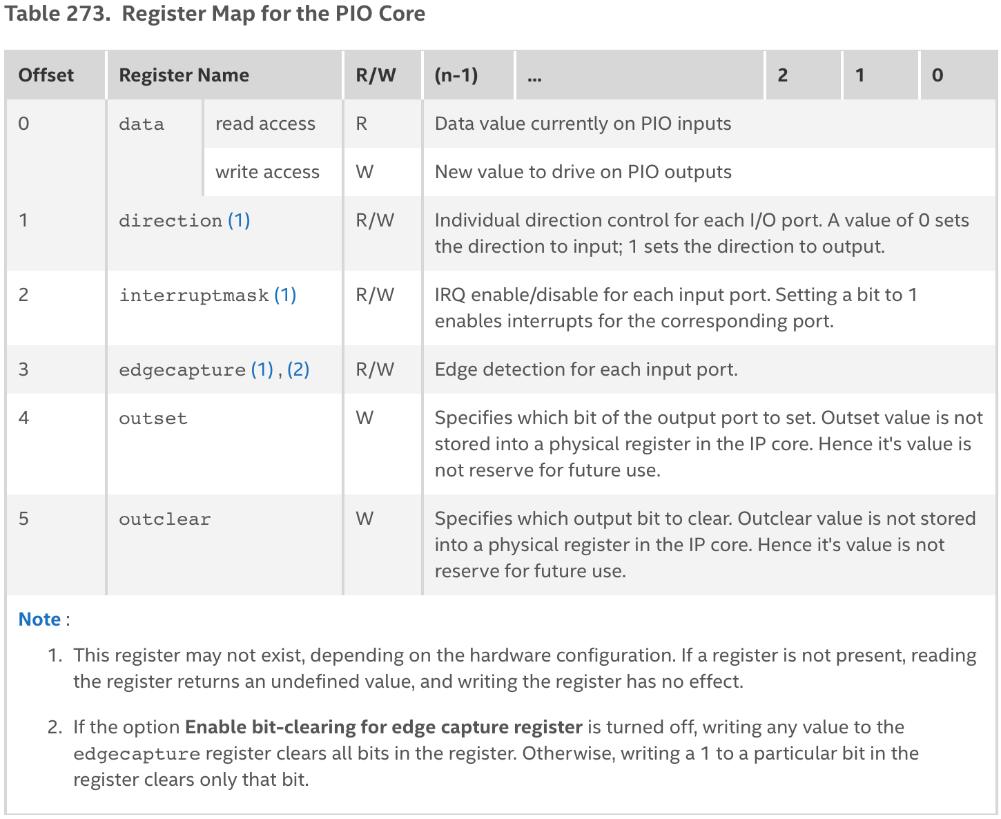
Fig. 38 Register map for the PIO module. Table 273 on page 311 in the Intel Embedded Peripherals IP User Guide.#
By writing and reading to these registers it is possible to configure the PIO module dynamically when running the system. The data register can be used to access the PIO core’s input and output ports. For a PIO module configured as a 10 bit wide output, which will be used to turn on and off LEDs, all LEDs can be turned on by using the following command:
IOWR(LED_PIO_BASE,0,0x3FF);
For a module that is configure as an input, e.g. the PIO module connected to the slide switches in the embedded systems project of this coures, the value of the slides swithces can be read by the following command:
int sw_data = IORD(LED_PIO_BASE,0);
To connect the slide switches and LEDs:
int sw_data = IORD(LED_PIO_BASE,0);
IOWR(LED_PIO_BASE,0,sw_data);
Update software#
We will now update the software application from EX5: A basic Nios II system to allow the slide switches to turn of and on the LEDs.
Modify the app.c as shown below.
#include <stdio.h>
#include "system.h" //access Nios II system info
#include "io.h" //access to IORD and IORW
#include "unistd.h" //access to usleep

int main(){
    printf("Hello, World!\n");
    int sw_data = 1;
    while(1){
        sw_data = IORD(PIO_SW_BASE,0);
        IOWR(PIO_LED_BASE,0,sw_data);
        usleep(100000); //sleep 100 us
    }
    return 0;
}
Recompile the software application, reprogram the FPGA with the updated hardware system, and then download the updated application. Verify that the application works by changing the positions of the slide switches.
Additional register access options#
Direct register access#
The Nios II CPU is a 32-bit architecture. That means that all registers of the memory mapped interface will be accessed as 32-bit wide registers. When using the IORD and IOWR macro functions, the word size is assumed to be 32-bit. While the registers are 32-bit wide, the addressing scheme can either be word oriented or byte oriented. The io.h header file also provides macro functions for byte-oriented addressing. The numbers 8, 16, 32 corresponds to the number of bits accessed by the macro.
IORD_8DIRECT(BASE, OFFSET)
IORD_16DIRECT(BASE, OFFSET)
IORD_32DIRECT(BASE, OFFSET)

IOWR_8DIRECT(BASE, OFFSET, DATA)
IOWR_16DIRECT(BASE, OFFSET, DATA)
IOWR_32DIRECT(BASE, OFFSET, DATA)
Here the BASE address corresponds to the module base address similar as for the IORD and IOWR, but the offset on the other hand now corresponds to the byte position. Fig. 39 illustrates the different addressing scheme. When using the IORD macro function, an OFFSET value of 0x1 refers to the second 32-bit register for the memory mapped module that is being accessed. To read the same register when using the byte oriented IORD_32DIRECT macro, the OFFSET value needs to correpsond to the lowest byte position of this register, that is 0x4.
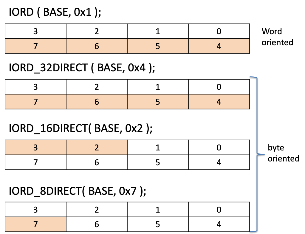
Fig. 39 HAL macro addressing scheme. The numbers indicate the byte positions within a 32-bit wide register.#
PIO macros#
The Nios II HAL also provides a dedicated set of macro functions for the PIO module in the altera_avalon_pio_regs.h header file. This file can be located in the /drivers/inc folder of the board support package project. The main content of the file is shown below.
#ifndef __ALTERA_AVALON_PIO_REGS_H__
#define __ALTERA_AVALON_PIO_REGS_H__

#include <io.h>

#define IOADDR_ALTERA_AVALON_PIO_DATA(base)           __IO_CALC_ADDRESS_NATIVE(base, 0)
#define IORD_ALTERA_AVALON_PIO_DATA(base)             IORD(base, 0)
#define IOWR_ALTERA_AVALON_PIO_DATA(base, data)       IOWR(base, 0, data)

#define IOADDR_ALTERA_AVALON_PIO_DIRECTION(base)      __IO_CALC_ADDRESS_NATIVE(base, 1)
#define IORD_ALTERA_AVALON_PIO_DIRECTION(base)        IORD(base, 1)
#define IOWR_ALTERA_AVALON_PIO_DIRECTION(base, data)  IOWR(base, 1, data)

#define IOADDR_ALTERA_AVALON_PIO_IRQ_MASK(base)       __IO_CALC_ADDRESS_NATIVE(base, 2)
#define IORD_ALTERA_AVALON_PIO_IRQ_MASK(base)         IORD(base, 2)
#define IOWR_ALTERA_AVALON_PIO_IRQ_MASK(base, data)   IOWR(base, 2, data)

#define IOADDR_ALTERA_AVALON_PIO_EDGE_CAP(base)       __IO_CALC_ADDRESS_NATIVE(base, 3)
#define IORD_ALTERA_AVALON_PIO_EDGE_CAP(base)         IORD(base, 3)
#define IOWR_ALTERA_AVALON_PIO_EDGE_CAP(base, data)   IOWR(base, 3, data)


#define IOADDR_ALTERA_AVALON_PIO_SET_BIT(base)       __IO_CALC_ADDRESS_NATIVE(base, 4)
#define IORD_ALTERA_AVALON_PIO_SET_BITS(base)         IORD(base, 4)
#define IOWR_ALTERA_AVALON_PIO_SET_BITS(base, data)   IOWR(base, 4, data)

#define IOADDR_ALTERA_AVALON_PIO_CLEAR_BITS(base)       __IO_CALC_ADDRESS_NATIVE(base, 5)
#define IORD_ALTERA_AVALON_PIO_CLEAR_BITS(base)         IORD(base, 5)
#define IOWR_ALTERA_AVALON_PIO_CLEAR_BITS(base, data)   IOWR(base, 5, data)


/* Defintions for direction-register operation with bi-directional PIOs */
#define ALTERA_AVALON_PIO_DIRECTION_INPUT  0
#define ALTERA_AVALON_PIO_DIRECTION_OUTPUT 1

#endif /* __ALTERA_AVALON_PIO_REGS_H__ */
It makes use of the IORD and IOWR macro functions to define new macro functions that hides the details of the internal register addresses. That is, if you would like to read the PIO module’s data registers, you can use the IORD_ALTERA_AVALON_PIO_DATA(base) macro. Example for accessing the PIO module reading the slide switches:
int data = IORD_ALTERA_AVALON_PIO_DATA(PIO_SW_BASE);
In this case you do not need to know the internal register address of the data registers.