EX8: A basic RTOS application#
In this part you will create a RTOS software application that will run two simple tasks. The job of the two tasks is to write “Hello from task1” and “Hello from task2” to the standard output.
The learning outcome of this problem is to:
Be able to setup an run a basic \(\mu\)C/OS-II RTOS system.
Be able to write RTOS task functions.
We will use the \(\mu\)C/OS-II (Micro-controller Operating System version 2) [uco] developed by Micrium in 1998. It is a priority-based pre-emptive multitasking operating system kernel. This means that it will always run the highest priority task that is ready. The kernel is ported to many processer, e.g., Nios-II, and supports all types from 8-bit to 64-bit.
As of February 28, 2020, the \(\mu\)C/OS-II comes with a permissive, open-source license model Link.
A commercial version of the kernel is also available under the name Cesium RTOS. A commercial license includes e.g., technical support. Link.
Another popular open-source real-time operating system for microcontrollers is FreeRTOS. Although FreeRTOS also is available for the Nios-II system, \(\mu\)C/OS-II comes integrated into the Nios-II software build tools, which makes is very easy to use. We will therefore use \(\mu\)C/OS-II in this project.
The \(\mu\)C/OS-II documentation is available as both HTML and PDF here: https://micrium.atlassian.net/wiki/spaces/osiidoc/overview.
It is recommended to read the chapter on real-time system concepts, as well as watching the RTOS related videos available on the FYS4220 webpage page: RTOS.
Before you start developing the application, you need to generate the required board support package and Makefile.
Board support package#
In Building the Software the software application used a board support package that included the basic drivers needed to control and communicate with the hardware platform. In this part we will use board support package which is extended with the \(\mu\)C/OS-II real-time kernel [uco]. This BSP provides access to \(\mu\)C/OS-II services for time management and task management, and /ntertask communication.
The Nios-II software build tools already includes the \(\mu\)C/OS-II real-time kernel. This can be added to the BSP by replacing the second argument used for the nios2-bsp command in Board Support Package with ucosii as shown below.
Navigate to the software folder of your project and create the folder app_rtos_bsp.
Create the board support package using the following command:
nios2-bsp ucosii app_rtos_bsp ../quartus/nios2_system.sopcinfo
Note
Your microcontroller system needs a timer module for the RTOS to work. This has already been included in the Microcontroller system built for the second part of the Project. It is therefore recommended to use this hardware for this exercise.
Makefile#
Under the software folder, create a new folder called app_rtos, and inside this folder a new for the moment empty file called app_rtos.c.
The Makefile is generated by running the following command from within the software folder:
nios2-app-generate-makefile.exe --bsp-dir app_rtos_bsp --src-dir app_rtos --app-dir app_rtos
Make sure the paths to the board support package folder, source and application folder corresponds to the relevant folders, and not to the folders used for the previous software application developed in Building the Software.
A Makefile should now be avaible inside the app_rtos folder.
Application code#
A \(\mu\)C\OS-II software application consists of the following parts:
Declaration of individual stack areas and stack priorities for each task
The task functions
A main function to create the task and start the multi-tasking system.
The stack area area is used by each task to hold the context for the task execution. This includes e.g., the local variables used by the stack as well as the context of any functions called by the task. If a task is preemted, its context is maintained in the task’s stack while the system executes another task. When the other task has completed, the original task executes again and continues from the context stored in its stack.
The stack space required for each task is not necessarily easy to estimate. It is therfore usual to start with a larger stack space and eventuelly reduce its size as the final system has been developed. E.g., if you call functions from a task, the stack usage will increase when it is active and decrease when it has completed. If a function calls a another function, the stack usage will increase with each nested function. It is therefore important to profile the stack usage during the development to optimize the stack size.
For the \(\mu\)C/OS-II the stack must be declared of the type OS_STK and must consit of contiguous memory locations. The declaration is made outside a function.
OS_STK MyTaskStack[stack_size];
The OS_STK is availble when including the includes.h header from the board support package
include.h
The includes.h can be found in the software/app_rtos_bsp/HAL/inc folder. It again includes header files relevant for using \(\mu\)OS-II.
#ifndef __INCLUDES_H__
#define __INCLUDES_H__

/*
*********************************************************************************************************
*                                                uC/OS-II
*                                          The Real-Time Kernel
*
*                        (c) Copyright 1992-1998, Jean J. Labrosse, Plantation, FL
*                                           All Rights Reserved
*
*                                           MASTER INCLUDE FILE
*********************************************************************************************************
*/

#ifdef __cplusplus
extern "C"
{
#endif /* __cplusplus */

#include    "os_cpu.h"
#include    "os_cfg.h"
#include    "ucos_ii.h"

#ifdef      ONT_GLOBALS
#define     ONT_EXT
#else
#define     ONT_EXT  extern
#endif

/*
*********************************************************************************************************
*                                             DATA TYPES
*********************************************************************************************************
*/

typedef struct {
    char    TaskName[30];
    INT16U  TaskCtr;
    INT16U  TaskExecTime;
    INT32U  TaskTotExecTime;
} TASK_USER_DATA;

/*
*********************************************************************************************************
*                                              VARIABLES
*********************************************************************************************************
*/

ONT_EXT  TASK_USER_DATA  TaskUserData[10];

/*
*********************************************************************************************************
*                                         FUNCTION PROTOTYPES
*********************************************************************************************************
*/

void   DispTaskStat(INT8U id);

#ifdef __cplusplus
}
#endif /* __cplusplus */

#endif /* __INCLUDES_H__ */
The example below shows an example where the stack aread has been declared for two tasks. The definition of the task priorities is also included.
#include "includes.h"

/* Definition of Task stacks */
#define TASK_STACKSIZE 2048  // Number of 32 bit words (e.g. 8192 bytes)
OS_STK task1_stk[TASK_STACKSIZE];
OS_STK task2_stk[TASK_STACKSIZE];

#define TASK1_PRIORITY 4
#define TASK2_PRIORITY 5
More information about the task stack can be found in the \(uC/OS-II\) documentation [Mic]. Direct link.
In addition to the stack area, you need to write the task functions. A task is typically an infinite loop function as shown below:
void YourTask (void *pdata)
{
   for (;;) {
	  /* USER CODE */
	  Call one of uC/OS-II's services:
	  OSFlagPend();
	  OSMboxPend();
	  OSMutexPend();
	  OSQPend();
	  OSSemPend();
	  OSTaskDel(OS_PRIO_SELF);
	  OSTaskSuspend(OS_PRIO_SELF);
	  OSTimeDly();
	  OSTimeDlyHMSM();
	  /* USER CODE */
   }
}
The example uses a for statement , but you could also use a while(1) statement.
A task looks like any other c function containing a return type and argument. However, since the task function is a continuous loop that is not meant to return any value, the return type must be declared void. An argument is passed to the code when the task first runs. Notice that the argument is a pointer to void, which means that an kind of data kan be passed to the task. The data to pass to the function is specified when the task is created and registerd with the multi-tasking system. In this project we will not pass any data to the function.
A task can be thought of as function that beleives it has the CPU to itself. In a multi-tasking system it is therefore importent to provide a mechanism for switching between tasks. The is referred to as a context switch and is taken care of by the schedular in the system.
The task is either in an active state where it is being executed by the CPU, or it can be in various inactive state where it is e.g., is waiting for an event or for the schedular to active the task. The various task states for \(\mu\)C/OS-II are described here and shown in Fig. 44.
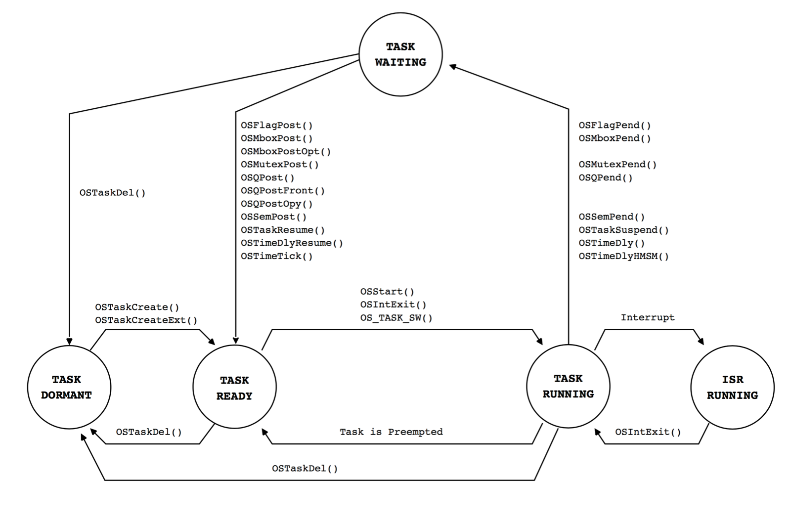
Fig. 44 The various task states a \(\mu\)C/-II task. Figure from the \(\mu\)C/OS-II manual.#
For a task to give up its use of the CPU, it needs to include a call to a function that blocks the execution of the task for a short moment. The list of functions that can be used for this purpose is shown in the example above. These functions are use to either wait for a given event or to block the execution of the task for a specified time period. While the task is blocked, the schedular can evaluate whether another task has higher priority and needs to run. If the task is never block, it will run continuously and never allow any other task to run.
The example below shows the function description for a task called task1 that prints to the standart output and then block for specified time using the OSTimeDlyHMSM function. In this case it blocks for 3 seconds. As a result the task will print to the standard output every 3 seconds.
void task1(void* pdata)
{
    while(1)
    {
        printf("Hello from task1\n");
        OSTimeDlyHMSM(0, 0, 3, 0) // (hours, minutes, seconds, milliseconds)
    }
}
After declaring the task stack sizes, the task priorities, and the tasks functions, the only thing left to to is to register the task to run in the system and to start the multi-tasking system. This is done within the main-function as shown in the example below for task1.
/* The main function creates two task and starts multi-tasking */
int main(void)
{
    //Create the task
    OSTaskCreateExt(task1, //Pointer to task function
                NULL, // pointer to argument that is passed to task
                (void *)&task1_stk[TASK_STACKSIZE-1], // Pointer to top of task stack
                TASK1_PRIORITY, // Task priority
                TASK1_PRIORITY, // Task ID - same as priority
                task1_stk, // Pointer to bottom of task stack
                TASK_STACKSIZE, // Stacksize
                NULL, // Pointer to user supplied memory
                0); // Various task options

    //Start the multi-tasking system.
    OSStart();
    return 0;
}
To complete the application add the code to describe the second task called task2 that will also print to the standard output very 3 seconds. Store the code in the app_rtos.c file. Compile the code and download it to the microcontroller system running on the FPGA. Connect to the JTAG UART using the nios2-terminal application to see a result similar to what is shown below.
$ nios2-terminal.exe
nios2-terminal: connected to hardware target using JTAG UART on cable
nios2-terminal: "USB-Blaster [USB-0]", device 1, instance 0
nios2-terminal: (Use the IDE stop button or Ctrl-C to terminate)

Hello from Task1
Hello from Task2
Hello from Task1
Hello from Task2
Hello from Task1
Hello from Task2
Hello from Task1
Hello from Task2
Hello from Task1
Hello from Task2
Hello from Task1
Hello from Task2
Hello from Task1
Complete code example
#include "includes.h"

/* Definition of Task stacks */
#define TASK_STACKSIZE 2048  // Number of 32 bit words (e.g. 8192 bytes)
OS_STK task1_stk[TASK_STACKSIZE];
OS_STK task2_stk[TASK_STACKSIZE];

#define TASK1_PRIORITY 4
#define TASK2_PRIORITY 5


void task1(void* pdata)
{
    while(1)
    {
        printf("Hello from task1\n");
        OSTimeDlyHMSM(0, 0, 3, 0) // (hours, minutes, seconds, milliseconds)
    }
}

void task2(void* pdata)
{
    while(1)
    {
        printf("Hello from task2\n");
        OSTimeDlyHMSM(0, 0, 3, 0) // (hours, minutes, seconds, milliseconds)
    }
}

/* The main function creates two task and starts multi-tasking */
int main(void)
{
    //Create the task
    OSTaskCreateExt(task1, //Pointer to task function
                NULL, // pointer to argument that is passed to task
                (void *)&task1_stk[TASK_STACKSIZE-1], // Pointer to top of task stack
                TASK1_PRIORITY, // Task priority
                TASK1_PRIORITY, // Task ID - same as priority
                task1_stk, // Pointer to bottom of task stack
                TASK_STACKSIZE, // Stacksize
                NULL, // Pointer to user supplied memory
                0); // Various task options

    //Create the task
    OSTaskCreateExt(task2, //Pointer to task function
                NULL, // pointer to argument that is passed to task
                (void *)&task2_stk[TASK_STACKSIZE-1], // Pointer to top of task stack
                TASK2_PRIORITY, // Task priority
                TASK2_PRIORITY, // Task ID - same as priority
                task2_stk, // Pointer to bottom of task stack
                TASK_STACKSIZE, // Stacksize
                NULL, // Pointer to user supplied memory
                0); // Various task options

    //Start the multi-tasking system.
    OSStart();
    return 0;
}