Project overview#
In this project you will build an embedded systems to measure vibration using an accelerometer. The overall functional requirement of the system is to continuously measure the acceleration in 3 axes and to communicate this stream of data to a PC. A simplified overview of the system is shown in Fig. 45.
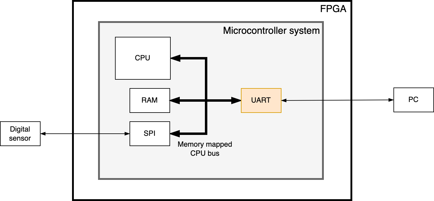
Fig. 45 Simplified overview of the embedded microcontroller system. The UART interface will be described in VHDL while the rest of the system will be generated using the Quartus Platform designer tool.#
The microcontroller system will run on the MAX10 FPGA on the DE10-Lite board. It will be based around a soft core CPU with the added peripherals required to communicate with the digital sensor and PC over standard serial interaces like UART[1], I2C[2], and SPI[3]. The digital accelerometer is available as a separate device on the DE10-lite board, that is, external to the FPGA.
A real-time operating system (RTOS) will finally be used to manage the main tasks running on the CPU, namely reading data from the digital sensor and sending this data over the UART to the PC.
The project will be divided into 3 main parts to guide you through the design of the system:
A suggested timeline for the progress of the project:
Part 1: 18. Sept. – 6. Oct.
Part 2: 9. Oct. – 27. Oct.
Part 3: 30. Oct. – 17. Nov.
Collaboration
I strongly recommendd that you find a partner to work together with on this project. Although you have to upload all the code to your own github repository, you should discuss your code and proposed solution with a colleague. You could even decide to share the workload of writing the code. E.g., dividing the task of writing individual parts of the code between you and then share the result. In this way, you will not only be responsible for your own project, but you will also contribute to the success of your colleague.