2.9. Testbenches#
For any development it is important to test and verify your solution before it is deployed in the field. This is no different for FPGAs where it is required to simulate your design before downloading and running it on the FPGA. In this section we will introduce the concept of testbenches in VHDL. Testbenches are the standard approach to simulate and verify your HDL design, and are used to apply stimuli to the inputs of a design and observe the outputs to verify correct behaviour. This is illustrated in figure Fig. 2.15.
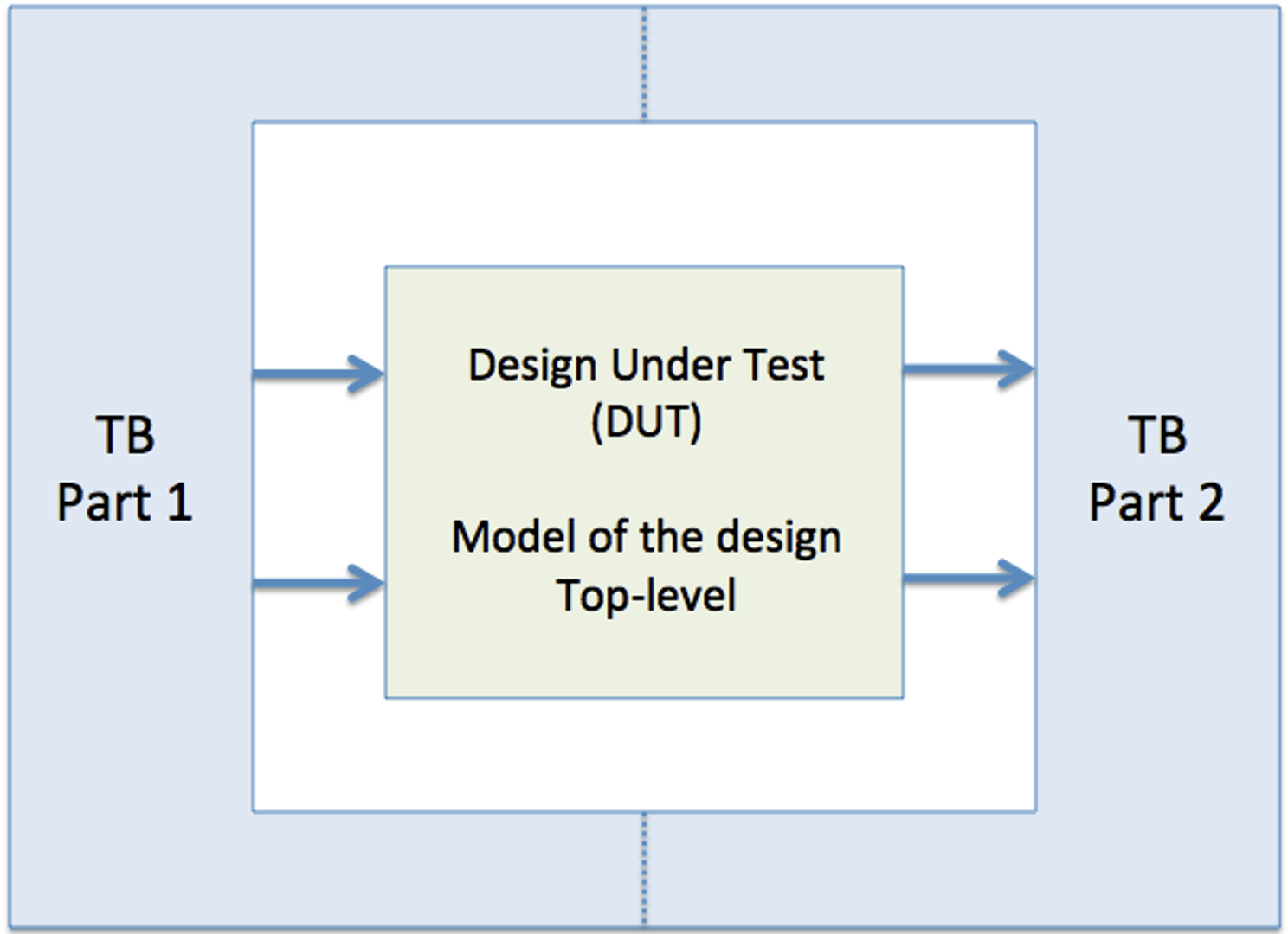
Fig. 2.15 A top-level view on testbenches.#
Testbenches can be written in VHDL. A VHDL testbench is not meant to run on hardware and can therefore take advantage of the full extent of the VHDL language. In contrast, the design under test, which will run on the FPGA, is restricted to VHDL written at the RTL-level level (see section Register Transfer Level (RTL)).
For a VHDL testbench it is e.g., possible to write a statement like shown below.
A <= '0';
wait for 20 ns;
A <= '1';
wait for 20 ns;
This will force a value to the signal A which first is ‘0’ for 20 ns and then ‘1’ for 20 ns as shown in figure Fig. 2.16.
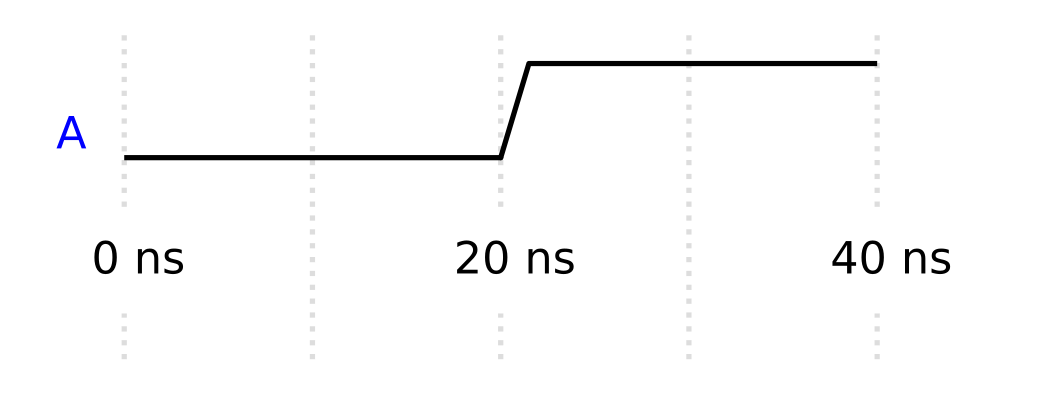
Fig. 2.16 A wave diagram of the code block above.#
This is a simple example of how e.g., an input stimuli can be described using VHDL. However, the synthesis tool is not able to translate the wait for 20 ns statement into any hardware resource on an FPGA. An FPGA does not have any inherently concept or understanding of time specified in this manner. This can only be done by providing the FPGA with a dedicated external clock signal. E.g., a signal that changes between a low and high value at a fixed regular interval. By connecting this clock signal to the internal registers of an FPGA, your design can now be synchronized to this signal, allowing it to update internal states and values on every internal states and values on every clock cycle.
2.9.1. Basic example: half adder#
Consider that you want to verify the correct behaviour of the half adder circuit shown in the code block below.
-- Filename: half_adder.vhd
library ieee;
use ieee.std_logic_1164.all;

entity half_adder is
port(
  A : in std_logic;
  B : in std_logic;
  SUM : out std_logic;
  COUT : out std_logic
  );
end entity;

architecture rtl of half_adder is

begin

  SUM <= A xor B;
  COUT <= A and B;

end architecture;
To build a testbench to verify this design you will make use to the structural description style introduced in section Structural. Since we already have described the half adder as a complete component with an entity and related architecture, we can simply reuse this design in a new VHDL file. The first step is to prepare the testbench VHDL-file. To distinguish the two files and entities, it is common to add tb as a prefix or postfix to the name of the design under test, and use this as the name of the testbench file. In this example add tb as a postfix.
-- Filename: halv_adder_tb.vhd
library ieee;
use ieee.std_logic_1164.all;

-- The entity declaration of
-- a testbench is empty.
entity half_adder_tb is
end entity;

architecture tb of half_adder_tb is

begin

end architecture;
This is the basic skeleton of a general VHDL file. However, different from the VHDL description of the component under test, the testbench has no ports, i.e., the entity declaration is empty. This makes sense if you compare to the diagram in figure Fig. 2.15. While the component under test may have both inputs and outputs, a testbench is not dependent on outside signal to run. All necessary functionality is generated within the architecture of the testbench. The entity declaration can therefore be left empty.
The testbench can in many ways be compared to a physical test setup on a lab bench, where signal generators are used provide test signals to a component, and an oscilloscope is used to monitor the outputs of the component. The purpose of the VHDL testbench is to act as the signal generator and oscilloscope, and simulate the behaviour of the VHDL design under test.
To include the VHDL design to be tested in the testbench, we can make use of the component and port map statements as shown in section Fig. 2.15, or we can take advantage of the possibility to do a so called direct instantiation. This uses a slightly different syntax for the port map statement at the benefit of not having to use the component statement.
-- Filename: half_adder_tb.vhd
library ieee;
use ieee.std_logic_1164.all;

-- The entity declaration of
-- a testbench is empty.
entity half_adder_tb is
end entity;

architecture tb of half_adder_tb is

  -- Signals to be connected to the
  -- design under test.
  signal A : std_logic;
  signal B: std_logic;
  signal SUM: std_logic;
  signal COUT: std_logic;

begin

  -- Direct instantiation of the design under test.
  -- The statement below means: use the entity half_adder
  -- which is compiled into the work library, and use the
  -- architecture named rtl which is found in that entity.
  -- Then connect the ports of that entity to the corresponding
  -- signals declared in the testbench.
  dut: entity work.half_adder(rtl)
    port map(
      A => A,
      B => B,
      SUM => SUM,
      COUT => COUT
    );


end architecture;
If not specified, the design will be compiled into a library called work. To reuse this design, we have to specify the name of the entity and the library where it can be found. An entity can be connected to multiple architectures, if this is the case, we also have to specify the name of the architecture, in this case rtl. Otherwise, it will automatically pick the last architecture which was compiled last. It is therefore a good habit to always specify the architecture, even though only one is available.
At the testbench level, we also need to declare signals that will be connected to the design under test, and that will provide stimuli to the inputs, and be monitored for expected values on the outputs.
The next step is to generate the appropriate stimuli to test the design. For this we will make use of the process statement. The process statement is described in more detail in the section VHDL Process. For now you can think of the process as a possibility to describe a sequential behaviour. While all statements inside the architecture of a VHDL file are concurrent statements, including the process statement, statements which are inside a process are read sequentially.
-- Filename: half_adder_tb.vhd
library ieee;
use ieee.std_logic_1164.all;

-- The entity declaration of
-- a testbench is empty.
entity half_adder_tb is
end entity;

architecture tb of half_adder_tb is

  -- Signals to be connected to the
  -- design under test.
  signal A : std_logic;
  signal B: std_logic;
  signal SUM: std_logic;
  signal COUT: std_logic;

begin

  -- Direct instantiation of the design under test.
  -- The statement below means: use the entity half_adder
  -- which is compiled into the work library, and use the
  -- architecture named rtl which is found in that entity.
  -- Then connect the ports of that entity to the corresponding
  -- signals declared in the testbench.
  dut: entity work.half_adder(rtl)
    port map(
      A => A,
      B => B,
      SUM => SUM,
      COUT => COUT
    );

  -- The process is a concurrent
  -- statement inside the architecture
  p_stimuli: process
  begin
    -- Inside the process, the statements are
    -- read sequentially and updated when the
    -- simulation time progresses.

    -- Set initial values for the inputs
    A <= '0';
    B <= '0';
    -- Progress simulation time
    wait for 50 ns;
    -- Update signal values
    A <= '1';
    B <= '0';
    -- Progress simulation time
    wait for 50 ns;
    A <= '0';
    B <= '1';
    -- Progress simulation time
    wait for 50 ns;
    A <= '1';
    B <= '1';
    -- Progress simulation time
    wait for 50 ns;
    -- stop the process
    wait; --halts the process forever.

  end process;

end architecture;
How to end a simulation
The stimuli process in a testbench is meant to run only once. To achieve this the process must use a wait statement at halt the process. Otherwise the process would continue to repeat it self as an infinit loop.
Supplementary suggested reading:
Chapter 5, section 5.7 in LaMeres [LaM19].
Direct link pdf-version Chapter 8, section 8.4 in LaMeres [LaM19]. Direct link html-version Direct link pdf-version
2.9.2. Simulate in Modelsim#
The testbench is now ready to be simulated using Modelsim. A simulation tool like Modelsim can be used to run the test bench and visualize its behaviour in a wave diagram format. Modelsim is a commercial tool, but a free version called Modelsim-Intel FPGA Starter Edition is included when downloading and installing the Quartus Prime Lite Edition. The starter edition is limited to 10000 lines of code. Adding more lines will reduce the performance of the simulator is significantly. An open-source alternative for the VHDL language is GHDL or GHDL on Github. The output of GHDL can be read and viewed by GTKWave. Since Modelsim is already included in Quartus Prime Lite, and since it is one of the most used tool in industry, we will continue to use Modelsim in this course.
In the following description the files are organized as shown below. Design files and testbench files are often separated into different folders. It is also good practice to create a separate folder where the simulations are run.
|-- fys4220_half_adder
    |-- src
        |-- half_adder.vhd
    |-- tb
        |-- half_adder_tb.vhd
    |-- sim
        |-- half_adder.mpf
A new project called half_adder is create in Modelsim (File-> New -> Project) and the folder sim is used as the Project Location as shown in Fig. 2.17
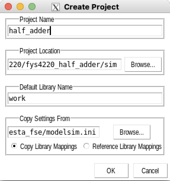
Fig. 2.17 Create Modelsim project.#
The source file and testbench file can be added to the project by choosing “Add Existing File” during the setup of the project, or through the menu bar (Project -> Add to Project -> Existing File).
The files have to be compiled in the correct order. half_adder_tb.vhd is dependent on half_adder.vhd, half_adder.vhd therefore has to be compiled first. To compile right click on the file and choose (Compile -> Compile Selected).
If Modelsim does not report any errors the simulation can now be started choosing (Simulate -> Start Simulation) from the menu and choosing the test bench unit half_adder_tb.vhd under the work library as shown in figure Fig. 2.18.
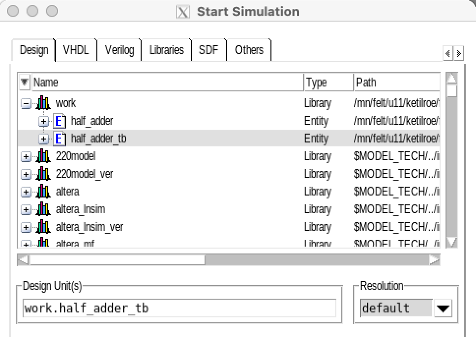
Fig. 2.18 Choose the test bench entity to start the simuliation.#
In Modelsim the wave viewer can be used to visualize the values of the input and outputs signals. If the wave viewer is not opened automatically this can be done by choosing (View -> Wave) from the menu bar. At this point no signals are added to the wave viewer. Mark the relevant signals, right click and choose “Add Wave” as shown in figure Fig. 2.19.
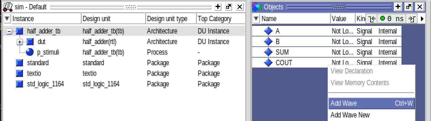
Fig. 2.19 Mark relevant signals to be added to the wave window.#
The simulation can now be run (Simulate -> Run -> Run -All) and you should see a similar results to the wave diagram shown in figure Fig. 2.20.
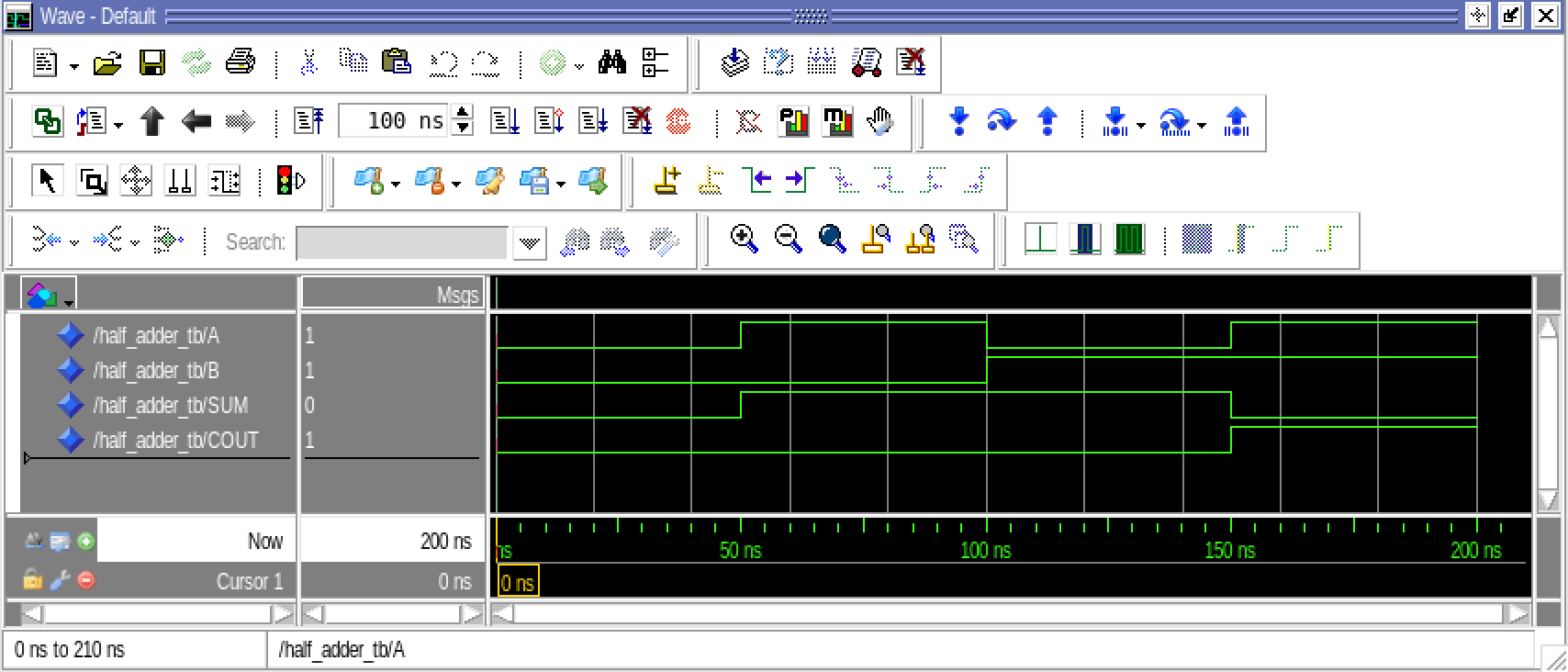
Fig. 2.20 The Modelsim wave viewer showing the result of the simulation of the half adder.#
To verify the correct behaviour of the half adder, we need to manually inspect the wave diagrams in the wave viewer. This is a very basic level of verification where only the stimuli on the inputs are automated.
2.9.3. Self-testing testbenches#
A manual verification of a wave diagram as discussed above will very quickly become impractical and time-consuming as your design’s complexity increases. It is therefore recommended to automate the simulation and verification as much as possible. Ideally, a testbench should run and complete reporting simply if the simulation passed the verification criteria or no. This means that you have to add checking into your testbench. One method is to make use of the assertion and report statements in VHDL.
2.9.3.1. Assert and report#
Report
The basic syntax of the report statement is:
report <message_string> [severity <severity_level>]
There are four severity levels that can be used (error, warning, note, and failure). Using severity level failure will stop the simulation, while the three others will allow the simulation to continue.
-- defined in the standard package with is included by default.
type severity_level is (note, warning, error, failure);
If the severity level is omitted, the report statement is implicitly assumed to be a note.
Given the following lines:
report "This is a note";
report "This is also a note" severity note;
report "This is a warning" severity warning;
report "This is an error" severity error;
report "This is a failure" severity failure;
a simulation in Modelsim will return:
# ** Note: This is a note
#    Time: 0 ns  Iteration: 0  Instance: /assert_tb
# ** Note: This is also a note
#    Time: 0 ns  Iteration: 0  Instance: /assert_tb
# ** Warning: This is a warning
#    Time: 0 ns  Iteration: 0  Instance: /assert_tb
# ** Error: This is an error
#    Time: 0 ns  Iteration: 0  Instance: /assert_tb
# ** Failure: This is a failure
#    Time: 0 ns  Iteration: 0  Process: /assert_tb/line__17 File: assert_tb.vhd
# Break in Process line__17 at assert_tb.vhd line 27
# Stopped at assert_tb.vhd line 27
Report statements are sequential statements, which means that they can only be used inside a VHDL Process or {ref} vhdl-packages-procedure statement.
Assert
The most basic syntax of the assert statement is:
assert condition;
This statement can be used to check if a condition is true or false. If the condition is true, the simulation will continue without prompting a message. If the condition is false, the simulation will prompt a message.
-- Here the condition is true and the simulation will continue without a prompt
assert true;
-- Here the condition is false and the simulation will break
assert false;
Assertion and report statements can be combined to check if an expected condition is met, or provide feedback in case it is not met.
The combined syntax is shown below followed by a basic example:
[label]: assert condition
         [ report <message_string> [severity <severity_level>]];
assert false report "This assert condition is false" severity warning;
When used in the half-adder test bench, the assert statement can be used to verify correct behaviour of the half-adder.
E.g., when the inputs A and B are both ‘0’, we expect the output signal SUM to also be ´0´.
-- Set the input signals to '0'
A <= '0';
B <= '0';
-- progress simulation to make sure the signal values are updated.
wait for 1 ns;
-- check if the output signal SUM is '0' as expected.
assert SUM = '0';
Adding the assertion statement checking for the condition SUM = ‘0’ will report and error if the condition is not met. You can easily test this by either changing your design or by testing for the condition SUM = ‘1’ instead. However, simply testing for the condition will only report the error but not provide any valuable debug information about what has gone wrong expect for the time at which the assertion was activate.
# ** Error: Assertion violation.
#    Time: 200 ns  Iteration: 0  Instance: /half_adder_tb
To increase the verbosity level you can add a report statement and also the appropriate severity level. To test this you can change the statement SUM <= A xor B; to SUM <= A or B in your half-adder design and demonstrate the assertion statement as shown below.
-- Set the input signals to '0'
A <= '0';
B <= '0';
-- progress simulation to make sure the signal values are updated.
wait for 1 ns;
-- check if the output signal SUM is '0' as expected and prompt a message if not.
assert SUM = '0'
  report "Incorrect value for signal SUM. Was " & to_string(SUM) & ", expected 0"
  severity warning;
Modelsim will then report the following message:
# ** Warning: Incorrect value for signal SUM. Was to 1, expected 0
#    Time: 200 ns  Iteration: 0  Instance: /half_adder_tb
Assert statements can be used both in the concurrent part of the architecture and inside a process.
architecture tb of test_tb is
begin

assert false report "This is a warning" severity warning;

process
begin
  assert false report "This is warning from inside a process" severity warning;
end process;

end architecture;
A note on simulation time and updating of signals
You might have noticed that a “wait for 1 ns” statement has been use in the examples above. The purpose of this statement is to allow the simulation time to progress in order for the signal assignments to be updated with their new values. Within a process each signal assignment is scheduled to be updated with its new value only when the process suspends.This can be achieved using a wait statement. When the process hits wait the statement, all the signal assignments up to that point will be updated, triggering the design under test to respond to these events, and eventually leading to that the states and outputs of the design under test also are updated. Adding a “wait for 1 ns” statement therefore allows the output SUM and COUT to be updated before the assertion statement is executed.
VHDL 2008 and type convertion
VHDL is a strongly type language. For the report statement this means that the value of SUM which is of the type std_logic needs to be convert to a string. If the testbench is compiled with VHDL 2008, it is possible to use the to_string function. For previous versions, the convertion had to be done using the more cryptic statement std_logic'image(SUM). Also, this statement did not support convertion from std_logic_vector. For ease of use, it is therefore recommended to use the to_string function supported in VHDL. This also supports std_logic_vector.
In Modelsim you can set the appropriate VHDL version in two ways:
Right click on the file to be compiled (Properties –> VHDL), or
through compile options in the menu bar for project wide setting (Compile –> Compile options)
The assertion statement also supports composite conditions.
assert (COUT = '1' and SUM = '0')
  report "Incorrect value for signal SUM and COUT," & to_string(COUT & SUM)
  severity warning;

-- or

assert (COUT & SUM) = "10"
  report "Incorrect value for signal SUM and COUT," & to_string(COUT & SUM)
  severity warning;
A complete stimuli process including assertion statements for the half adder example is shown below.
  -- The process is a concurrent
  -- statement inside the architecture
  p_stimuli: process
  begin
    -- Inside the process, the statements are
    -- read sequentially and updated when the
    -- simulation time progresses.
    report "Starting simulation of half_adder";

    -- Set initial values for the inputs
    A <= '0';
    B <= '0';
    -- Progress simulation time and check values
    wait for 50 ns;
    assert (COUT = '0' and SUM = '0');
      report "(COUT & SUM) was " & to_string(COUT & SUM) & ", expected 00"
      severity warning;

    -- Update signal values
    A <= '1';
    B <= '0';
    wait for 50 ns;
    -- Progress simulation time and check values
    wait for 50 ns;
    assert (COUT = '0' and SUM = '1');
      report "(COUT & SUM) was " & to_string(COUT & SUM) & ", expected 00"
      severity warning;

    -- Update signal values
    A <= '0';
    B <= '1';
    -- Progress simulation time and check values
    wait for 50 ns;
    assert (COUT = '0' and SUM = '1');
      report "(COUT & SUM) was " & to_string(COUT & SUM) & ", expected 00"
      severity warning;

    -- Update signal values
    A <= '1';
    B <= '1';
    -- Progress simulation time and check values
    wait for 50 ns;
    assert (COUT = '1' and SUM = '0');
      report "(COUT & SUM) was " & to_string(COUT & SUM) & ", expected 00"
      severity warning;

    report "Simulation complete";
    -- stop the process
    wait; --halts the process forever.

  end process;
If the half adder design is correct, Modelsim will report the following when running the process above.
# ** Note: Starting simulation of half_adder
#    Time: 0 ns  Iteration: 0  Instance: /half_adder_tb
# ** Note: Simulation complete
#    Time: 250 ns  Iteration: 0  Instance: /half_adder_tb
Modifying the half adder design to include and intentional error, e.g., changing the statement SUM <= A xor B; to SUM <= A or B, Modelsim will report the following.
# ** Note: Starting simulation of half_adder
#    Time: 0 ns  Iteration: 0  Instance: /half_adder_tb
# ** Warning: (COUT & SUM) was 11, expected 00
#    Time: 250 ns  Iteration: 0  Instance: /half_adder_tb
# ** Note: Simulation complete
#    Time: 250 ns  Iteration: 0  Instance: /half_adder_tb
In this case it catches and reports the design error.
2.9.4. Defining a clock source#
For synchronous designs you need to define a clock source for your testbench. A clock is a signal that changes between ‘0’ and ‘1’ at a fixed interval. This can be described using a simple process as shown below.
process
begin
  clk <= '0';
  wait for 10 ns;
  clk <= '1';
  wait for 10 ns;
end process
If the signal is declared with an initial value it can also be described as shown below.
architecture tb of test is
  signal clk: std_logic := 0;
begin

  clk <= not clk after 10 ns;

end architecture;
However, for both of these descriptions the clock will start to run immediately and will never end. A recommended solution is therefore to use and enable signal to turn on and of the clock.
architecture tb of test is
  signal clk : std_logic;
  signal clk_enable : boolean := false;
  signal clk_period : time := 20 ns;

begin

  -- invert the value of the signal clk after a certain time (half clock period) when
  -- the enable signal is true, otherwise the clk signal shall remain 0.
  -- This creates a signal that changes its value every half clock cycle when the clk_ena
  -- signal is true, and remains at 0 when the clk_ena signal is false, that is, a clock
  -- with the frequency equal to 1/clk_period
  clk <= not clk after clk_period/2 when clk_ena else '0';

  p_stimuli: process
  begin
    -- set default values

    -- enable clock
    clk_ena <= true;
    -- set sequence of stimuli signals

    -- disable clock
    clk_ena <= false;
    -- stop the process
    wait;
  end process;

end architecture;
2.9.5. Supporting videos#
The following video discusses testbenches in VHDL. The first part of the video until about 14:11, presents some of the basic concepts similar to what has also been introduced in the text on this page. After 14:11 the video continues to cover a few more topics related to more advanced self-testing testbenches. These topics will make more sense as the course progresses and you learn more about VHDL packages and sub-programs. The examples in the video are different from the example shown above – the video was recorded before this page was written. In the future the plan is to update the video to make it more aligned with the content on this page.