P1: UART controller#
In this part of the project you will design the UART controller that will be used to communicate data between the microcontroller system in the FPGA and the PC.
The learning outcome of this problem is to:
Aquire basic knowledge of the UART serial communication protocol.
Gain experience in architecting a VHDL module.
Learn how to write a memory mapped CPU interface to connect a custom VHDL peripheral to the CPU bus.
Gain additional experience in writing test benches, including using a dedicated verification framework/library.
A top level block diagram of a suggested design for the UART controller (uart.vhd) is shown in Fig. 46. This solution consists of three submodules:
The TX module which is responsible for transmitting the 8-bit data serially on the UART TX line.
The RX module which is responsible for sampling the UART RX line and receiving the 8-bit data.
The processor memory mapped interface that will be used to control and communicate with the TX and RX modules from software running on the CPU.
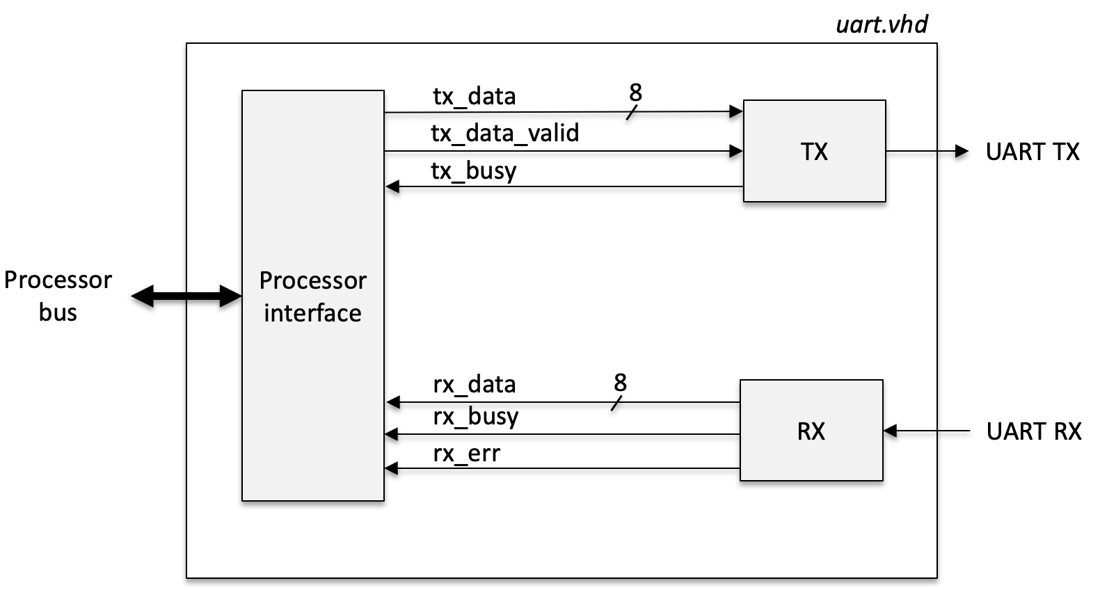
Fig. 46 Simplified top level block diagram of the UART controller. It consists of 3 submodules, the CPU interace, UART TX, UART RX.#
Your job is to write the VHDL description for the uart.vhd. This work will be divided in 3 parts:
Before you start to design the respective modules, you should first make sure you understand the basics of the UART protocol.
UART data transmission#
UART is an abbreviation for Universal Asynchronous Receiver-Transceiver. It is used for one-to-one asynchronous bi-directional serial communication. In its most basic form it uses two lines for communication, one for transmitting (TX) and one for receiving (RX).
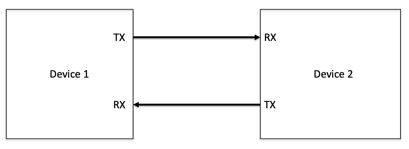
Fig. 47 UART connection between two devices.#
Asynchronous means that the communication interface does not make use of a dedicated line for a clock signal. Both the receiver and transmitter therefore needs to be aware of the frequency used to transmit and receive data, referred to as the baud rate.
Data is transmitted in the form of a UART packet consisting of a start bit, a data frame, an optional parity bit, and 1 or 2 stop bits. The UART data packet is illustrated in figure Fig. 48.
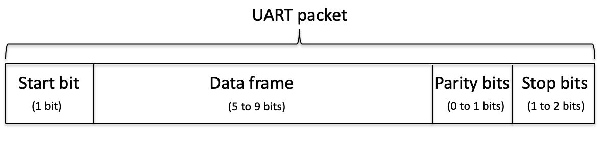
Fig. 48 The General UART packet.#
Fig. 49 show an example of a TX transmission with 1 start bit, 8 data bits, no parity bit, and 1 stop bit. The TX line is usually held high when no data is transmitted. Start of transmission is initiated by pulling the TX line low for the duration of a bit period. This corresponds to the start bit position. The data frame is transmitted with the least significant bit first. A transmission is completed by pulling the TX line high for the duration of one bit period – the stop bit.
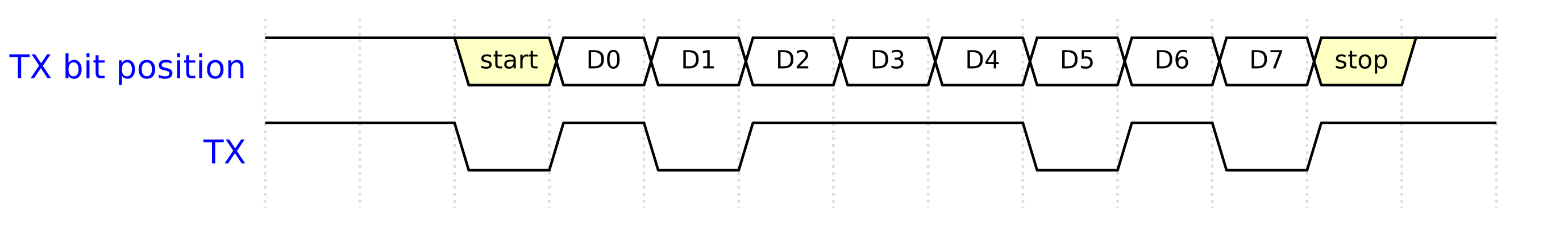
Fig. 49 Example of an 8 bit data frame transmitted on the TX line with 1 stop bit, no parity bit, and 1 stop bit.#
What is value of the 8 bit data frame transmitted in the figure above?
From LSB to MSB the data bits are : 1 0 1 1 1 0 1 0
Since we are more used to read the value with the MSB to the left the reversed order is shown below.
From MSB to LSB the data bits are : 0 1 0 1 1 1 0 1
This corresponds to the the byte “5D” in hexadecimal format.
Additional reading material
AnalogDialogue gives a nice overview of the UART communication protocol:
Baud rate#
In communication system, the baud rate is the rate at which symbols or information is transferred. The unit is symbols per second. The baud rate is related to raw bit rate which can be expressed in bits per seconds. For a digital system with only two possible states (0 and 1) the baud rate is equivalent to the bit rate.
A commonly used baud rate for a UART transmission is 115200 bits/s. This means that a bit is transferred every 8.68 \(\mu\)s. The transfer of a full UART data frame with 1 start bit, 8 data bits, and 1 stop bit is therefore 10*8 \(\mu\)s = 86.8 \(\mu\)s.
TX module#
Your first task will be to write the VHDL description for the TX module. The format of the UART packet for this project will be 1 start bit, 8 data bits, and 1 stop bit, as shown in Fig. 50. And the baud rate will be 115200 bits/s. bit.
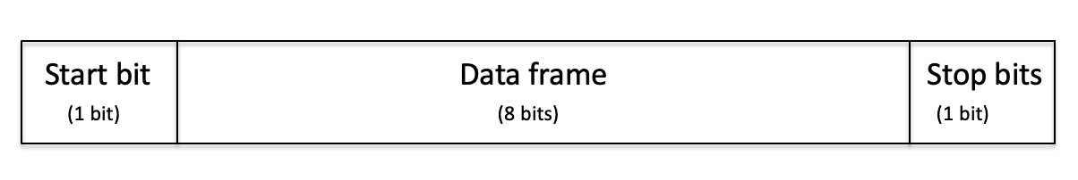
Fig. 50 The UART packet used for this project has 1 start bit, 8 data bits, and 1 stop bit.#
The main task of the TX module is to serialize an 8-bit data word on to the TX line at the specified baud rate of 115200 bits/s. The module will run on the 50 MHz system clock and have an asynchronous active low reset.
A few words about design practice!
It is often tempting to start to code immediately without thinking much about how to structure the module. This may work well for very simple modules but will very quickly lead to difficulties for more complex design. It is therefore recommended that you first spend some time to design the architecture of your module. This includes how to split the required functionality into smaller sub-modules, and how these sub-modules are interconnected. This will lead to a modular and hirarchical design that is easier to verify and understand.
In general it is also a good practice to strive to follow the KISS principle – keep it simple stupid. This principle states that most systems work best if they are kept simple rather then complicated; therefore, simplicity should be a key goal in design, and unnecessary complexity should be avoided.
Identifying the various sub-functions of your system and splitting your design into respecitve modules can therefore help to reduced the complexity of each module, and thus reduced the probability of errors.
Both the TX and RX modules have a few common or similar sub-functions:
State machine: A finite state machine to control to start and stop transmission. See EX4: State machine for the case of the TX module. A slightly modified version must be designed for the RX module.
Bit counter: A module that keeps track of the number of bits that have been transferred or received.
Shift register: A module that loads an 8-bit data word into a 10-bit internal data buffer (including also the start and stop bit) before shifting these 10 bits serially on to the TX line (TX module); or that serially shifts in 10-bits (start bit, 8-bit data, stop bit) from the RX line and stores these bits in an internal 10-bit data buffer (RX module).
Baud rate generator: A module that generates an internal signal with a period corresponding to the required baud rate. This signal will drive the transmit/receive data shift register and bit counter.
The bit counter and baud rate generator can be reused for both the TX and RX module as their functionality is the same for both cases. On the other hand, the controlling state machine and shift register must be adapted to each case, although with only marginal difference.
Considering the four sub-modules introduced above, a suggested architecture of the TX module is shown in Fig. 51.
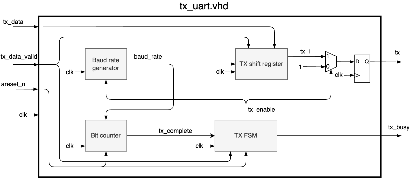
Fig. 51 Internal architecture of the TX module. The diagram is created using the Draw.io Integration in VS Code, and the source file can be downloaded from here. You can edit the file in VS Code or online at www.draw.io. A desktop version of Draw.io is also available on Github.#
The corresponding ports of the top level entity is listed in the table below.
Port name |
Direction |
Type |
Width |
Comment |
|---|---|---|---|---|
clk |
in |
std_logic |
1 |
50 MHz system clock |
areset_n |
in |
std_logic |
1 |
Asynchronous active low reset |
tx_data |
in |
std_logic_vector |
8 |
Input data to be transmitted on the RX line |
tx_data_valid |
in |
std_logic |
1 |
Valid data on tx_data. Start transmission. |
tx_busy |
out |
std_logic |
1 |
Module busy, transmission ongoing (active high) |
tx |
out |
std_logic |
1 |
UART TX output |
To start the tranmission of data the tx_data_valid input is pulled to a high level for one system clock cycle when the data is made available on the input tx_data. This condition loads tx_data into the internal data buffer of the TX shift register, and triggers the state machine to move from its idle state to its transmit state.
Write the VHDL descriptions for each of the sub-modules and included them in the TX module tx_uart.vhd. You should already have written the VHDL description for the TX FSM in EX4: State machine. Ideally, each of the sub-modules should be verified with individual test benches. However, since we only have a limited amount of time available, an acceptable shortcut is to write a test bench for the TX module and run incremental simulations as you write and include the individual sub-modules. Start by including the TX FSM module and run a simulation with only this module included. Add the baud rate generator and rerun the simulation to check that you have a running baud rate signal. Then add the bit counter module. After each baud rate period, this module should increment a counter. When the counter has reach the required number of bits (10), puts a pulse of one system clock cycle on the tx_complete port. Rerun the simulation to verify this behaviour. Finally, add the TX shift regiser. After each baud rate period, the internal TX data buffer is shifted one position. The data is shifted out with the least significant bit first.
Write a stimuli process in the test bench that sets a data value on the tx_data input and then toggles the tx_data_valid port for one system clock cycle. For the TX module the main verification method is to study the wave diagram.
RX module#
After writing the VHDL description for the TX module, writing the RX module should be very similar. The main difference of course being that the RX module now must convert the incoming serial data on the RX line to an 8-bit parallel data vector. The format of the UART packet and the baud rate will be the same as for the TX module.
Start by designing a top level architecture for the RX module inspired by the architecture for the TX module. Create a similar digram to the one in Fig. 51.
Review of design architecture required before writing the code!
The diagram of your design architecture must be reviewed by the course instructors before you start to write the VHDL description of the RX module. Export the diagram in the format png and add it to your Github repository. Open and issue on Github and assign the issue to the course instructors. Provide a link to your diagram.
I encourage you to discuss and prepare the diagram together with one of the other students in the course. You can then submit one diagram together, naming the responsible persons in the issue description.
To help you identify some of the differences, a proposed microarchitecture of the rx_shift_reg.vhd module is shown in Fig. 52. Different from the TX UART, the RX uart must sample the input RX in the center of the bit period. This can be done by detecting the rising edge of the signal baud_rate and use this event as an enable for the shift register. When all bits have been received, the rx_complete signal can be used to register the rx_data to the output, and to signal an error if either the start or stop bit have values other than expected.
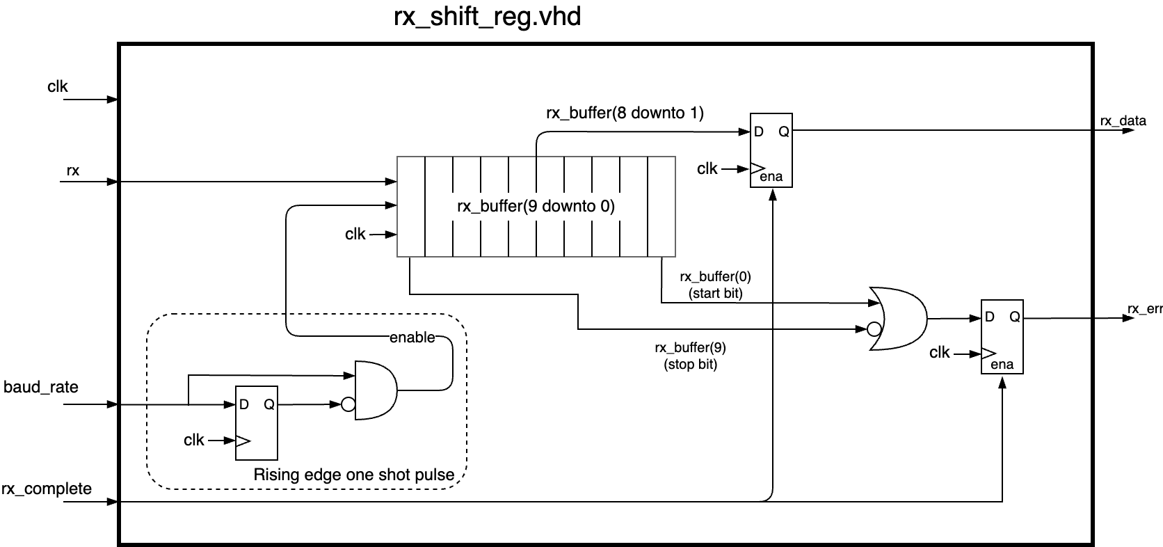
Fig. 52 The diagram shows the microarchitecture for the RX shift register.#
An example of how to describe the serial shifting of bits is shown in the code block below.
-- rx_buffer is declared as a 10-bit std_logic_vector
p_serial_shift: process(clk)
  begin
    if rising_edge(clk) then
      if enable = '1' then
        rx_buffer <= rx & rx_buffer(9 downto 1);
      end if;
    end if;
end process;
As already mentioned, the bit counter and baud rate generator modules can be reused without modifications. The few noticable difference are listed below:
Transmission is now started on a high to low transition on the RX line. The RX FSM should therefore also read the RX input and move to the receive state when the RX line goes to ‘0’.
The shift register should now shift in 10 bits, including start bit, 8 data bits, and a stop bit.
The data on the RX line should be sampled in the center of a baud period when the data is expected to be stable.
The suggested list of top level ports for the RX module’s entity description is shown in the table below.
Port name |
Direction |
Type |
Width |
Comment |
|---|---|---|---|---|
clk |
in |
std_logic |
1 |
50 MHz system clock |
areset_n |
in |
std_logic |
1 |
Asynchronous active low reset |
rx_data |
out |
std_logic_vector |
8 |
Received data |
rx_err |
out |
std_logic |
1 |
Flag incorrect stop or start bit (active high). |
rx_busy |
out |
std_logic |
1 |
Module busy, reception ongoing (active high) |
rx |
in |
std_logic |
1 |
UART RX input |
Write the VHDL description for the RX module and a test bench to verify expected behaviour. When testing the TX module, it was reasonable easy write a test bench that assigned data to the tx_data port and then toggled the tx_data_valid port for one clock cycle. However, for the RX module you know need to provide a stream of data on the RX input port corresponding to a 10 bit serial transmission at the expected baud rate. This can of course be done setting the respective values and waiting for a baud period like shown below.
p_stimuli: process
begin
  -- rx high when no activity.
  rx <= '1';
  wait for 100 ns;
  -- Start transactions
  -- start bit
  rx <= '0';
  wait for C_BIT_PERIOD;
  -- data bit 0
   rx <= '1';
  wait for C_BIT_PERIOD;
  -- data bit 1
  rx <= '0';
  wait for C_BIT_PERIOD;
  .
  .
  .
  -- data bit 7
  rx <= '0';
  wait for C_BIT_PERIOD;
  -- stop bit
  rx <= '1';
  wait for C_BIT_PERIOD;

end process
However, this is not so flexible if you want to test multiple transactions. Then you would have to repeat all these lines for each transaction. This is a perfect case for writing a procedure that can be reused easily. To see how this can be done, study the example in Section 2.14.3.2.
The choice of method is up to you. Either the more simple approach shown above, or the procedure example.
Processor interface#
In this section you will write the memory mapped register interface that will allow the software running on the microcontroller system to access and controll your UART module.
Reading tip!
Make sure you study Section 3.3 Memory mapped interfaces before you continue.
To connect the TX and RX modules to a microcontroller system we need define a set of registers that can be accessed by the the CPU. These registers should contain information about the data to be transmitted and received, and the status of the modules. A suggested set of registers can be:
An 8-bit data transmit register (mm_tx_data)
A 8-bit data receive register (mm_rx_data)
A 8-bit status register (mm_status)
Status register
The status registeri should consist of the following information:
Bit 0: tx_data_valid
Bit 1: tx_busy
Bit 2: rx_busy
Bit 3: rx_err
Bit 4: tx_irq
Bit 5: rx_irq
Bit 6–7: Not in use
The tx_data_valid is the bit used to start a transaction for the UART TX module. This bit can be set when the CPU writes to the tx_data register. It should remain high until the TX module has started a transmission, and then be automatically reset to ‘0’ from the internal logic of this processor interface. How can you detect when a transmission has started?
Solution
By monitoring the tx_busy signal. We know from the TX state machine that the tx_busy signal is initially low when there is no activity, and that it goes high after the state machine has detected a high value on tx_data_valid. Therefore, the tx_data_valid bit position can be reset when a rising edge is detected on the TX busy signal.
-- Reset tx_data_valid when tx busy goes high
if tx_busy = '1' and mm_tx_busy = '0' then
  tx_data_valid <= '0'; --reset tx data valid
end if;
Where mm_tx_busy is the registered version of the TX busy signal in the processor interface. And mm_tx_busy is defined as an alias:
alias mm_tx_busy : std_logic is mm_tx_status(1);
To control the flow of data you will use two interrupt signals, tx_irq and rx_irq. These interrupts are used to indicate when a transmission has been completed on the UART TX and when the UART RX has received data. Can you think of a solution that would set these bits accordingly?
Solution
The signal that indicates whether a module transmitting og receiving data is the busy signal. When the busy signal changes from high to low, this means that the operation has been completed. Assuming that the busy signals are registered in the status register (called mm_status here), the following implementation can be used:
if rising_edge(clk) then
  mm_tx_busy <= tx_busy;
  mm_rx_busy <= rx_busy;

  if mm_tx_busy = '1' and tx_busy = '0' then
    tx_irq <= '1';
  end if;
  if mm_rx_busy = '1' and rx_busy = '0' then
    rx_irq <= '1';
  end if;
.
.
.
These two bits will be used to signal an interrupt to the CPU. The CPU can only receive one interrupt from the module, and the two interrupts must therefore be or’ed
irq <= tx_irq or rx_irq;
The CPU can check which interrupt bit has been set by reading the statuts register. The CPU also needs to reset the IRQ bits when the interrupt has been registerd. This can be done by for example making a write transaction to the status register.
if we = '1' then
  case addr is
    when "10" =>
      rx_irq <= '0';
      tx_irq <= '0';
.
.
.
You will see how this can be utilized in software when we come to the RTOS part of the project.
The Nios II is a 32-bit CPU with a 32-bit wide data and instruction bus. The data read and write lines of the processor interface therefore needs to be 32 bits wide even though fewer bits are needed in the case of the UART. This can be solved as shown below.
signal mm_tx_data : std_logic_vector(7 downto 0);
signal mm_rx_data : std_logic_vector(7 downto 0);

architecture rtl of uart is
.
.
.
elsif rising_edge(clk) then
  -- Write to registers
  if we = '1' then
    case addr is
      when "00" =>
      mm_tx_data <= wdata(7 downto 0);
.
.
.
  if re = '1' then
    case addr is
      when "01" =>
      rdata <= x"000000" & mm_rx_data;
.
.
.
You task is to write the register interface and connect the TX and RX module. Create a file called uart.vhd and include both the TX and RX modules as well as the register interface.
Connect the relevant ports from the TX and RX modules to the respective register locations.
Warning
If you want to make use of the test bench example provided in the next section it is important that you adhere to the ordering of the bits in the status regiser as described above and the naming of the ports in the top level entity shown below.
If you use different names or locations, you will need to modify the test bench accordingly.
The top level entity of the uart.vhd should be as shown below:
entity uart is
  generic (
    GC_SYSTEM_CLK : integer := 50_000_000;
    GC_BAUD_RATE  : integer := 115_200
    );
  port (
    clk    : in  std_logic;
    arst_n : in  std_logic;
    -- processor interface
    we     : in  std_logic;
    re     : in  std_logic;
    wdata  : in  std_logic_vector(31 downto 0);
    rdata  : out std_logic_vector(31 downto 0);
    addr   : in  std_logic_vector(1 downto 0);
    -- uart interface
    rx     : in  std_logic;
    tx     : out std_logic;
    -- interrupt interface
    irq    : out std_logic
    );
end uart;
Verifying the UART#
To verify the behaviour of the UART we need to test both the processor interface and the TX and RX lines. This would require you to write support procedures to control and monitor each port according to the Avalon bus specification and the UART packet structure and timing. An example procedure for stimulating the RX port was already shown in Section 2.14.3.2.
Similar procedures would also be needed to test the TX interface and the Avalon Memory Mapped register interface. The procedures can then be used in the test bench if they are placed either in the declaration area of the test bench’s architecture, or in a separate VHDL package.
Writing dedicate test procedures can be very valuable for the process of learning, but it can also be time-consuming. When you have first nailed the concept of writing such test procedurece, it is generally more efficient to make use of already existing libraries. There is no point “reinventing the wheel” when someone else has already written these procedures and made them available in open source verification libraries like e.g., Universal VHDL Verification Methodology (UVVM) library available from www.github.com/uvvm and www.uvvm.org, or Open source VHDL verification methodology (OSVVM) available from www.osvvm.rog. In this course we will demonstrate the use of UVVM.
Reading tip!
If you would like to read more about UVVM here are a few relevant links:
In the video below, Espen Tallaksen from EmLogic gives an introductory talk on UVVM. UVVM is an extensive library and we will limit our use to the reduced version called UVVM Light (UVVM/UVVM_Light), and its respective Bus Functional Models (BFM) for the UART and Avalon interfaces. The most relevant part of the video are the first 15 minutes. After this, more advanced concepts which are less relevant for this course are covered. Of course, you are welcome to watch the full presenation if you like.
These first 15 minutes cover the basics of UVVM exemplified by testing a UART. The test procedures that you will use in your project are different from the ones use in the example, but the concepts are the same. The example uses so called bus functional models to interface and test the UART. A BFM is a VHDL description that models the signaling protocal of the various interface. Similar to the procedure used to stimulate the RX port in the previous section. In the example the processor to UART interface a simple bus interface (SBI). You will instead use an Avalon interface in your project, which is a bus interface specific for the Nios-II processor.
The relevant procedures that will be used from the UVVM library for this project are:
avalon_mm_write()
avalon_mm_read()
avalon_mm_check()
from the Avalon BFM, and
uart_transmit()
uart_receive()
uart_expect()
from the UART BFM.
UVVM resources
All documents can be found in the UVVM_Light/doc folder of the UVVM Github repository.
Setting up the simulation#
The description below assume that you will have the following directory structure. If you have different directory structure you must adopot the commands and decsription below accordingly.
- project
  - UVVM_Light (will be cloned from Github)
  - tb
    - uart_tb.vhd
  - src
    - uart_rx.vhd
    - uart_tx.vhd
    - uart.vhd
  - scripts
    - compile_src.do
    - run.do
  - simulation
To run a simulation using the UVVM Light, you first have to download the library from Github. Navigate to your project directory and clone the repository.
git clone https://github.com/UVVM/UVVM_Light.git
Add the following basic VHDL description to your UART test bench (
uart_tb.vhd). This is the most basic setup to needed to activate the use of the UVVM library.
library ieee;
use ieee.std_logic_1164.all;
use ieee.numeric_std.all;

-------------------------------------------------------------------------------
-- UVVM Utility Library
-------------------------------------------------------------------------------
library uvvm_util;
context uvvm_util.uvvm_util_context;
-- The context statement is a way to group together packages that you would
-- like to include in your test bench.
-- The uvvm context can be found here:
-- https://github.com/UVVM/UVVM_Light/blob/master/src_util/uvvm_util_context.vhd
-- Have a look at the following description on how to use context
-- https://www.doulos.com/knowhow/vhdl/vhdl-2008-incorporates-existing-standards/#context
-------------------------------------------------------------------------------

entity uart_tb is
end uart_tb;


architecture tb of uart_tb is
begin

  -- Main test sequencer
  p_main_test_sequencer : process
    constant C_SCOPE : string := "TB seq.";
  begin
    ----------------------------------------------------------------------------------
    -- Set and report init conditions
    ----------------------------------------------------------------------------------
    report_global_ctrl(VOID);
    report_msg_id_panel(VOID);
    enable_log_msg(ALL_MESSAGES);

    ------------------------
    -- Begin simulation
    ------------------------
    log(ID_LOG_HDR, "Start Simulation of TB for UART controller", C_SCOPE);


    ------------------------
    -- End simulation
    ------------------------
    report_alert_counters(FINAL);  -- Report final counters and print conclusion for simulation (Success/Fail)
    log(ID_LOG_HDR, "SIMULATION COMPLETED", C_SCOPE);
    wait;
  end process;
end architecture;
Open Modelsim and change directory to the Simulation directory (*File->Change Directory).
In the Modelsim Transcript window write the following command to compile the UVVM library.
do ../UVVM_Light/script/compile.do ../UVVM_Light .
A library called uvvm_util should now be visible in the Library window of Modelsim.
Compile the basic UART test bench provided above (uart_tb.vhd):
vcom -2008 ../tb/uart_tb.vhd
Initiate the simulation
vsim uart_tb
Run the simulation
run -all
If successful, you should see the following output at the end of the Transcript window:
# UVVM:      ====================================================================================================================================================================
# UVVM:      *** FINAL SUMMARY OF ALL ALERTS ***
# UVVM:      ====================================================================================================================================================================
# UVVM:                                REGARDED   EXPECTED  IGNORED      Comment?
# UVVM:                NOTE         :      0         0         0         ok
# UVVM:                TB_NOTE      :      0         0         0         ok
# UVVM:                WARNING      :      0         0         0         ok
# UVVM:                TB_WARNING   :      0         0         0         ok
# UVVM:                MANUAL_CHECK :      0         0         0         ok
# UVVM:                ERROR        :      0         0         0         ok
# UVVM:                TB_ERROR     :      0         0         0         ok
# UVVM:                FAILURE      :      0         0         0         ok
# UVVM:                TB_FAILURE   :      0         0         0         ok
# UVVM:      ====================================================================================================================================================================
# UVVM:      >> Simulation SUCCESS: No mismatch between counted and expected serious alerts
# UVVM:      ====================================================================================================================================================================
# UVVM:
# UVVM:
# UVVM:
# UVVM:
# UVVM: ID_LOG_HDR                         0.0 ns  TB seq.                        SIMULATION COMPLETED
# UVVM: -------------------------------------------------------------------------------------------------------------------------------------------------------------------------
The same information should also be printed to the file _Log.txt in the simluation directory. If any alerst would occur during the simulation they will be printet to the Transcript window as well as the file _Alert.txt in the simulation directory.
It is now time to add and make use of the relevant Bus Functional Models to test your UART component. The full VHDL test bench is shown below.
library ieee;
use ieee.std_logic_1164.all;
use ieee.numeric_std.all;

-------------------------------------------------------------------------------
-- UVVM Utility Library
-------------------------------------------------------------------------------
library uvvm_util;
context uvvm_util.uvvm_util_context;

-- The UVVM library contains a bus functional models (BFMs) for the Avalon memory mapped
-- interface, and the UART TX and RX protocol
-- These two package provide access to procedures that can be used to write to and read from an Avalon Memory mapped
-- interface, and to read and write to a UART.
use uvvm_util.uart_bfm_pkg.all;
use uvvm_util.avalon_mm_bfm_pkg.all;
-------------------------------------------------------------------------------

entity uart_tb is
end uart_tb;


architecture sim of uart_tb is

  constant GC_SYSTEM_CLK : integer := 50_000_000;
  constant GC_BAUD_RATE  : integer := 115_200;

  constant C_BIT_PERIOD : time := 1 sec / GC_BAUD_RATE;
  constant C_CLK_PERIOD : time := 1 sec / GC_SYSTEM_CLK;

  signal clk_ena : boolean   := false;
  signal clk     : std_logic := '1';
  signal arst_n  : std_logic := '1';
  signal rx      : std_logic;
  signal tx      : std_logic;
  signal irq     : std_logic;


  --------------------
  -- Avalon BFM setup
  --------------------

  -- The UVVM avalon bus functional model (BFM) has a certain set of default configuration parameters that needs to be updated in order to be used in this project. Use the following settings.
  constant C_AVALON_MM_BFM_CONFIG : t_avalon_mm_bfm_config := (
    max_wait_cycles          => 10,
    max_wait_cycles_severity => TB_FAILURE,
    clock_period             => C_CLK_PERIOD,
    clock_period_margin      => 0 ns,
    clock_margin_severity    => TB_ERROR,
    setup_time               => C_CLK_PERIOD/4,  -- recommended
    hold_time                => C_CLK_PERIOD/4,  -- recommended
    bfm_sync                 => SYNC_ON_CLOCK_ONLY,
    match_strictness         => MATCH_STD_INCL_Z,
    num_wait_states_read     => 1,
    num_wait_states_write    => 0,
    use_waitrequest          => false,
    use_readdatavalid        => false,
    use_response_signal      => false,
    use_begintransfer        => false,
    id_for_bfm               => ID_BFM,
    id_for_bfm_wait          => ID_BFM_WAIT,
    id_for_bfm_poll          => ID_BFM_POLL
    );

  -- The UVVM BFM package uses a record type to group the MM IF signals
  -- Create interface signal of record type t_avalon_mm_if;
  -- See avalon_mm_if_bfm_pkg.vhd for definition
  -- Records are similar to structures in C, and are often used to define a new VHDL type.  This new type contains a group of signals that the user desire to e.g. simplify an interface.
  -- The t_avalon_mm_if needs to be constrained as some of the record members are defined as std_logic_vector without specifying the length of the vector.
  signal avalon_mm_if : t_avalon_mm_if(address(1 downto 0),
                                       byte_enable(3 downto 0),
                                       writedata(31 downto 0),
                                       readdata(31 downto 0));

  --------------------
  -- UART BFM setup
  --------------------

  -- Similar to the Avalon MM BFM, the UART BFM has set of default
  -- configuration parameters that needs to be updated for this specific test bench.
  -- In particular the baud rate (bit_time), number of bits, and parity and
  -- stop bits.
  constant C_UART_BFM_CONFIG_DEFAULT : t_uart_bfm_config := (
    bit_time                              => 8.68 us,  -- 115 200
    num_data_bits                         => 8,
    idle_state                            => '1',
    num_stop_bits                         => STOP_BITS_ONE,
    parity                                => PARITY_NONE,
    timeout                               => 20 * C_BIT_PERIOD,
    timeout_severity                      => error,
    num_bytes_to_log_before_expected_data => 0,
    match_strictness                      => MATCH_EXACT,
    id_for_bfm                            => ID_BFM,
    id_for_bfm_wait                       => ID_BFM_WAIT,
    id_for_bfm_poll                       => ID_BFM_POLL,
    id_for_bfm_poll_summary               => ID_BFM_POLL_SUMMARY,
    error_injection                       => C_BFM_ERROR_INJECTION_INACTIVE
    );


  -- To test the error flag of the RX module, we can active error injection on
  -- these bits.
  -- Testing stop bit. This will set a low value during the stop bit period.
  constant C_BFM_ERROR_INJECTION_ACTIVE : t_bfm_error_injection := (
    parity_bit_error => false,
    stop_bit_error   => true
    );

  -- Create a new set of defaults for error injection purpose
  constant C_UART_BFM_CONFIG_STOP_ERROR : t_uart_bfm_config := (
    bit_time                              => 8.68 us,
    num_data_bits                         => 8,
    idle_state                            => '1',
    num_stop_bits                         => STOP_BITS_ONE,
    parity                                => PARITY_NONE,
    timeout                               => 20 * C_BIT_PERIOD,  -- will default never time out
    timeout_severity                      => error,
    num_bytes_to_log_before_expected_data => 0,
    match_strictness                      => MATCH_EXACT,
    id_for_bfm                            => ID_BFM,
    id_for_bfm_wait                       => ID_BFM_WAIT,
    id_for_bfm_poll                       => ID_BFM_POLL,
    id_for_bfm_poll_summary               => ID_BFM_POLL_SUMMARY,
    error_injection                       => C_BFM_ERROR_INJECTION_ACTIVE
    );


  -- The UART receive BFM can be terminated prematurely by setting the
  -- terminate_loop to 1. We do not use this functionality.
  signal terminate_loop : std_logic := '0';

begin
  -- Generate clock signal
  clk <= not clk after C_CLK_PERIOD / 2 when clk_ena else '0';

  -- Connect UART module
  UUT : entity work.uart(rtl)
    generic map(
      GC_SYSTEM_CLK => GC_SYSTEM_CLK,
      GC_BAUD_RATE  => GC_BAUD_RATE
      )
    port map(
      clk    => clk,
      arst_n => arst_n,
      -- processor interface
      we     => avalon_mm_if.write,
      re     => avalon_mm_if.read,
      addr   => avalon_mm_if.address,
      wdata  => avalon_mm_if.writedata,
      rdata  => avalon_mm_if.readdata,
      irq    => irq,
      -- UART interface
      rx     => rx,
      tx     => tx
      );


  -- Main test sequencer
  p_main_test_sequencer : process
    constant C_SCOPE               : string                       := "TB seq.";
    variable tx_data               : std_logic_vector(31 downto 0);
    variable rx_data               : std_logic_vector(31 downto 0);
    variable uart_bfm_send_data    : std_logic_vector(7 downto 0) := (others => '0');
    variable uart_bfm_receive_data : std_logic_vector(7 downto 0) := (others => '0');
    variable mm_reg_addr           : unsigned(1 downto 0)         := (others => '0');

  begin
    ----------------------------------------------------------------------------------
    -- Set and report init conditions
    ----------------------------------------------------------------------------------
    -- Increment alert counter as one warning is expected when testing writing
    -- to ID register which is read only
    --increment_expected_alerts(warning, 0);
    -- Print the configuration to the log: report/enable logging/alert conditions
    report_global_ctrl(VOID);
    report_msg_id_panel(VOID);
    enable_log_msg(ALL_MESSAGES);
    disable_log_msg(ID_POS_ACK);        --make output a bit cleaner

    ------------------------
    -- Begin simulation
    ------------------------
    log(ID_LOG_HDR, "Start Simulation of TB for UART controller", C_SCOPE);
    log(ID_SEQUENCER, "Set default values for I/O and enable clock and reset system", C_SCOPE);
    -- default values
    arst_n  <= '1';
    clk_ena <= true;                    --Enable the system clk
    rx      <= '1';   -- set initial default value of rx line.
    wait for 5 * C_CLK_PERIOD;

    -----------------------
    -- Toggle reset
    ----------------------
    log(ID_SEQUENCER, "Activate async. reset for clk periods", C_SCOPE);
    arst_n <= '0', '1' after 5 * C_CLK_PERIOD;
    wait for C_CLK_PERIOD * 10;


    ----------------------
    --Test TX
    ----------------------
    -- Write to processor interface to initiate transactions
    log(ID_SEQUENCER, "Testing TX", C_SCOPE);
    tx_data     := x"000000AA";
    mm_reg_addr := "00";                -- data register
    avalon_mm_write(mm_reg_addr, tx_data, "MM IF Write transaction to UART data reg -- enabeling TX transaction", clk, avalon_mm_if, C_SCOPE, shared_msg_id_panel, C_AVALON_MM_BFM_CONFIG);

    -- Use UART BFM to monitor RX line and check that received data matches tx_data
    uart_receive(uart_bfm_receive_data, "UART receive transaction", tx, terminate_loop, C_UART_BFM_CONFIG_DEFAULT, C_SCOPE, shared_msg_id_panel);
    check_value(uart_bfm_receive_data, tx_data(7 downto 0), warning, "Checking tx data");

    -- wait for irq signal to be activated indicating transmitting complete
    await_value(irq, '1', 0 ns, C_BIT_PERIOD, error, "Interrupt expected", C_SCOPE);

    -- Read status register to check for tx irq
    mm_reg_addr := "10";
    avalon_mm_check(mm_reg_addr, x"00000010", "MM IF transaction to verify correct TX IRQ value in status register", clk, avalon_mm_if, warning, C_SCOPE, shared_msg_id_panel, C_AVALON_MM_BFM_CONFIG);
    -- write any value to the status register to reset the tx irq
    avalon_mm_write(mm_reg_addr, x"00000000", "MM IF Write transaction to reset irq in status register", clk, avalon_mm_if, C_SCOPE, shared_msg_id_panel, C_AVALON_MM_BFM_CONFIG);

    wait for 100*C_CLK_PERIOD;

    ----------------------
    --Test RX
    ----------------------
    log(ID_SEQUENCER, "Testing RX", C_SCOPE);
    -- USE UART BFM to send data to RX line
    uart_bfm_send_data := x"55";
    uart_transmit(uart_bfm_send_data, "UART TX", rx, C_UART_BFM_CONFIG_DEFAULT, C_SCOPE, shared_msg_id_panel);

    -- wait for irq signal to be activated indicating receive completed
    await_value(irq, '1', 0 ns, C_BIT_PERIOD, error, "Interrupt expected", C_SCOPE);

    -- Read rx register of UART moduel to check if data has been received.
    mm_reg_addr        := "01";
    avalon_mm_check(mm_reg_addr, x"00000055", "MM IF transaction to verify correct value in RX data register", clk, avalon_mm_if, warning, C_SCOPE, shared_msg_id_panel, C_AVALON_MM_BFM_CONFIG);
    -- Read status register to check for rx irq
    mm_reg_addr        := "10";
    avalon_mm_check(mm_reg_addr, x"00000020", "MM IF transaction to verify correct RX IRQ value in status register", clk, avalon_mm_if, warning, C_SCOPE, shared_msg_id_panel, C_AVALON_MM_BFM_CONFIG);
    -- Reset tx irq
    avalon_mm_write(mm_reg_addr, x"00000000", "MM IF Write transaction to reset irq in status register", clk, avalon_mm_if, C_SCOPE, shared_msg_id_panel, C_AVALON_MM_BFM_CONFIG);

    ----------------------
    --Test RX with error injection for stop bit.
    ----------------------
    log(ID_SEQUENCER, "Testing RX with error injections on stop bit", C_SCOPE);
    -- USE UART BFM to send data to RX line
    uart_bfm_send_data := x"55";
    uart_transmit(uart_bfm_send_data, "UART TX", rx, C_UART_BFM_CONFIG_STOP_ERROR, C_SCOPE, shared_msg_id_panel);
    ----------------------

    -- wait for irq signal to be activated indicating receive completed
    await_value(irq, '1', 0 ns, C_BIT_PERIOD, error, "Interrupt expected", C_SCOPE);

    -- First read rx register of UART moduel to check if data has been received.
    mm_reg_addr := "01";
    avalon_mm_check(mm_reg_addr, x"00000055", "MM IF transaction to verify correct value in RX data register", clk, avalon_mm_if, warning, C_SCOPE, shared_msg_id_panel, C_AVALON_MM_BFM_CONFIG);
    -- Then read status register and check that rx_err and rx irq bits are set.
    mm_reg_addr := "10";
    avalon_mm_check(mm_reg_addr, x"00000028", "MM IF transaction to verify correct value in status register", clk, avalon_mm_if, warning, C_SCOPE, shared_msg_id_panel, C_AVALON_MM_BFM_CONFIG);
    -- Reset tx irq
    avalon_mm_write(mm_reg_addr, x"00000000", "MM IF Write transaction to reset irq in status register", clk, avalon_mm_if, C_SCOPE, shared_msg_id_panel, C_AVALON_MM_BFM_CONFIG);


    wait for 5*C_CLK_PERIOD;

    clk_ena <= false;
    report_alert_counters(FINAL);  -- Report final counters and print conclusion for simulation (Success/Fail)
    log(ID_LOG_HDR, "SIMULATION COMPLETED", C_SCOPE);


    wait;
  end process;


end architecture;