2.3. Design units and structure#
Why should we use a Hardware Description Language (HDL)? Today the FPGA development tools may provide a possibility to draw and connect the logic building blocks by using a schematic editor through a graphical user interface like shown in Fig. 2.2.
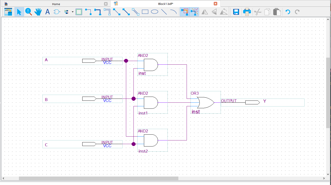
Fig. 2.2 Quartus Prime Lite schematic editor.#
While this may seem intuative and provide a pleasing visual overview of your design, it comes with some disadvantages like lack of portability across platforms, lack of maintainability, and potentially a very complex diagram for large designs. The better solution is therefore to describe the design using a Hardware Description Languages (HDLs) like e.g. VHDL or Verilog. Using VHDL, the design in Fig. 2.2 can be described as shown below.
library ieee;
use ieee.std_logic_1164.all;

-- The entity describes the interface
-- between the outside and the internal
-- functionality.
entity majority_voter is
  port(
    A   : in  std_logic;
    B   : in  std_logic;
    C   : in  std_logic;
    Y   : out std_logic
    );
end majority_voter;

-- The architecture describes the internal functionality
architecture design of majority_voter is
begin

-- This is the main functionality.
Y <= (A and B) or (A and C) or (B and C);

end architecture;
The overhead in number of lines for this simple design may seem large. However, the more complex the design, the smaller the relative overhead. The VHDL description above can be stored as a readable text format in a file with the extension .vhd. This comes with the added bonus that the file can be put under version control using e.g. Git. An essential and important practice when developing code based projects. In the following sections we will explain the basic structure of a VHDL file.
2.3.1. VHDL as a model of digital system#
VHDL can be looked at as a model of a digital system and provides a powerful alternative to schematic based design. A change (transition) on the input may lead to a new system state and consequently a change of the output after a given time delay. VHDL can be used to describe and simulate concurrent events.
Some important remarks
VHDL is a HARDWARE DESCRIPTION LANGUAGE.
A VHDL model is translated into actual hardware and mapped onto an FPGA. This is in contrast to other high level languages where the code is executed on predefined hardware like a processor. While code running on a processor is executed sequentially, a VHDL description mapped onto an FPGA is a physical implementation in, and of hardware resources – where multiple instances can be realized and operate concurrently. This opens for massive parallelization of functinality, one of the main advantages of FPGAs compared to standard CPUs.
When refering to the execution of a VHDL code, this means that the VHDL model is being simulated (e.g. by software running on a computer).
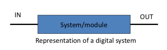
At the top level, the structure of a VHDL design can be viewed as black-box approach, where the two main parts of any hierarchical design are the
black box,
and the “stuff” that goes into the black box (e.g., other black boxes)
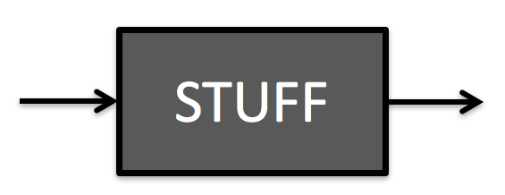
Fig. 2.3 Black box approach.#
2.3.2. Entity and architecture#
In VHDL the black box is referred to as the entity and the “stuff” that goes inside the entity is referred to as the architecture body of that entity. An image that might help to visualize this concept is to consider a chip or chip package like the one shown in Fig. 2.4. From the outside the chip can be view as a black box as its internal functionality is not directly visible.
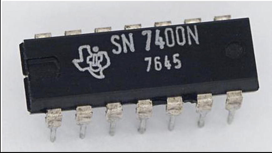
Fig. 2.4 The entity describes the interface to the outside world and. E.g., the pins of a chip that can be used to connect to its inside functinality. Image credit: Audrius Meskauskas, distributed under CC BY-SA 3.0, wikipedia.#
The pins of the chip provide a port or interface to the inside architecture of the chip as illustrated in Fig. 2.5.
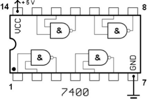
Fig. 2.5 The architecture describes the functionality of the circuit inside the entity (chip package). Image credit: Audrius Meskauskas, distributed under CC BY-SA 3.0, wikipedia.#
The entity and architecture approach enables the use of hierarchical structure (modularity) and the reuse of previously written code. A module is referred to by its inherently simple black box representation rather than by the details of its inside circuitry or functionality. The chip analogy works very well for a simple non-hierarchical design, where the entity describes the pins (their name and direction), and the architecture describes the functionality connected to these pins. However, for more complex designs, an hierarchical approach may be needed. An entity description is therefore not limited to describe the top level interface of a chip, but can also be used to describe the interface of internal modules of a chip or design, not connected directly to the pins of a chip.
2.3.3. The basic structure of a VHDL File#
The basic structure of a VHDL-file can be divided in three parts as shown in Fig. 2.6:
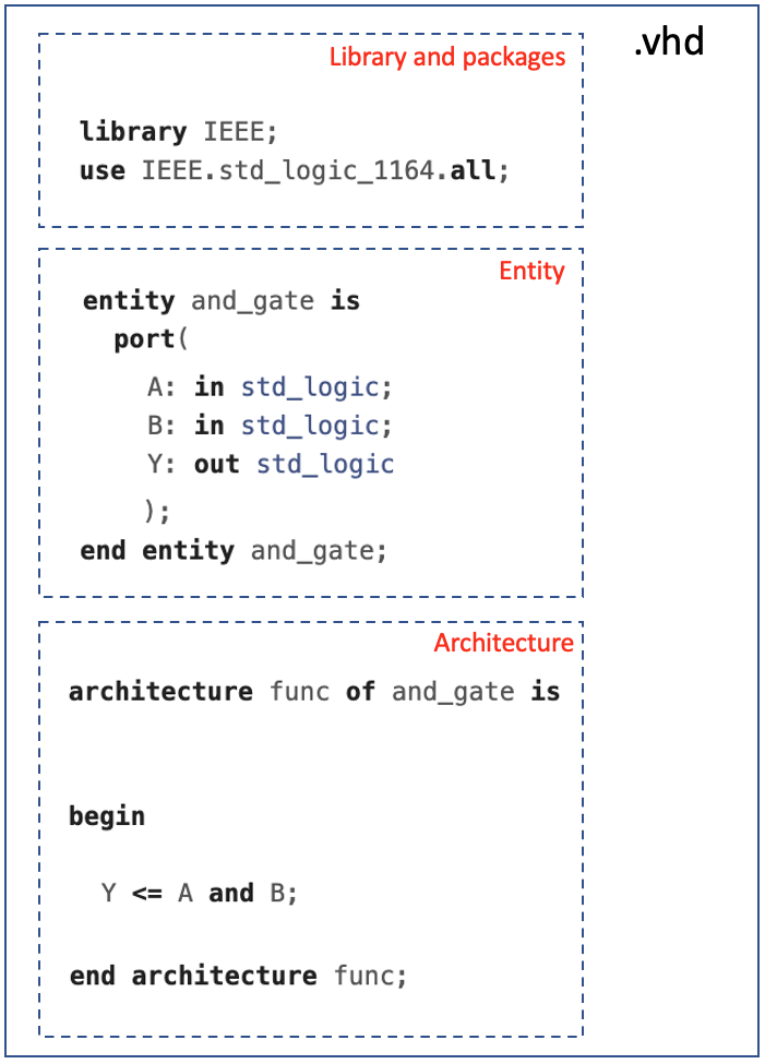
Fig. 2.6 The basic structure of a VHDL-file consist of a section where relevant libraries and packages are defined, the entity declaration, and the architecture description.#
2.3.3.1. Library and packages#
The Library and package part was already introduced in section Section 2.2, and is where you list or declare any packages that are needed to gain access to specific features of the VHDL language. Like the data type std_logic from the std_logic_1164 of the IEEE library, which is one of the most commonly used types in VHDL.
library IEEE;
IEEE.std_logic_1164.all;
2.3.3.2. Entity#
An entity declaration should start with the keyword entity and end with keyword end. The identifier in an entity declaration names the module so that it can be referred to later. A port clause is then used to list and name each of the entity’s ports, which together form the interface of the entity. Items enclosed by < > are mandatory items, while [ ] are optional.
entity <identifier> is
  port(
    -- list of input and output ports
    -- with direction, and type:
    -- <identifier> : <mode> <type>
    );
end [entity] [identifier];
Each port has a type which specifies the kind of information that is communicated, and a mode which specifies how information flows into or out from the entity. The valid modes for an entity are listed in the table below and illustrated in Fig. 2.7.
Mode |
Description |
|---|---|
In |
Flow into the entity |
Out |
Flow out of the entity (no feedback) |
Buffer |
Flow out of the entity (feedback allowed) |
Inout |
for bi-directional signals |
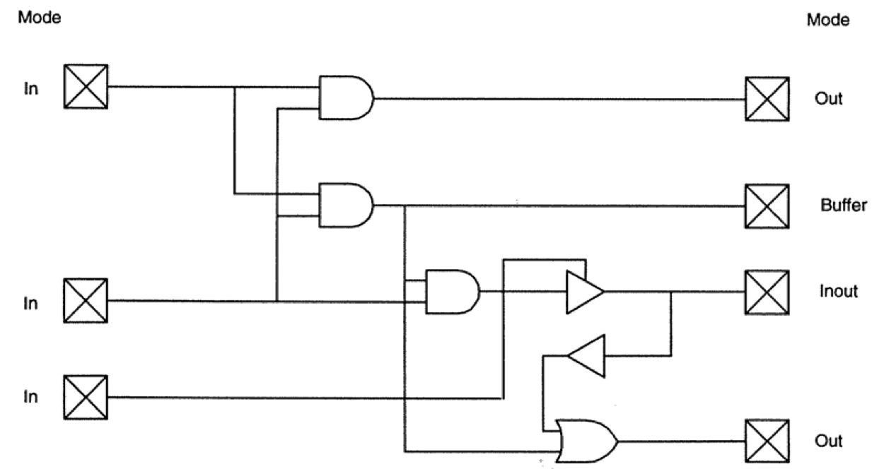
Fig. 2.7 Entity port modes.#
2.3.3.3. Architecture#
While entity describes the interface or external representation of the circuit, the architecture describes what the circuit actually does – its internal functionality. An architecture body generally operates on values from the input ports, generating values to be assigned to output ports. An architecture needs to be connected to an entity, this achieved with the <entity_identifier> in the first line of the architcture declaration. Items enclosed by < > are mandatory items, while [ ] are optional.
architecture <identifier> of <entity_identifier> is
-- Declarative area
begin
-- Concurrent statement area
end [architecture] [identifier]
A complete example is shown below for the basic description of an AND gate. This VHDL description can be synthesized and programmed onto an FPGA. The only thing which is missing is to specify which physical pin of the FPGA that shall be connected to which port in the entity declaration. This must be specified by the user and provided to the synthesis tool before compilation.
library IEEE;
use IEEE.std_logic_1164.all;

entity and_gate is
  port(
    A: in std_logic;
    B: in std_logic;
    Y: out std_logic -- Notice: no semicolon on last item!
    );
end entity and_gate;

architecture rtl of and_gate is

begin

Y <= A and B;

end architecture rtl;
2.3.4. Comments#
In VHDL, when a double dash (
--) is used, any text to the right will be treated as a comment and will not be interpreted by the compiler. From VHDL-2008 it is also possible to comment out blocks using /* and */.Supplementary suggested reading
Chapter 5, section 5.4 in LaMeres [LaM19].
Direct link html-version
Chapter 3 in Mealy and Teppero, Free Range VHDL.