2.10. VHDL Process#
In VHDL a process can be used to model both
combinational logic,
and synchronous logic.
The process statement is particularly useful and needed when writing test benches. The process statement itself is a concurrent statement identified by its label, its sensitivity list, a declaration area and a begin-end area containing instructions executed sequentially. Within the process each line of code is read sequentially and assignments are scheduled to be updated/effectuated next time the process is suspended. The general syntax for a process is shown below. Elements in square brackets are optional.
[process-label] : process[( sensitivity list )] [is]
  -- declaration area
  begin
    -- sequential statement part
end [process] [process-label];
The process-label is an optional identifer of the process, e.g. a name given to the process, which can be used e.g. to easily find/identify the process when performing simulations in Modelsim.
2.10.1. Supporting videos#
The 3 following videos gives an introduction to process in VHDL. The first video discusses how the process statement works and how it can be used to write combinational logic. The second video then follows up with a testbench to simulate the combinational process from video 1. These two videos also demonstrates how a process can be used differently when writing code for synthesis and for a testbench purpose. Finally, the third video covers the synchronous process, and shows an example of how to write a process that describes and simulates a 1-bit memory element (D flip-flop). It also covers how to implement both synchronous and asynchronous resets, and a short discussion on the actual hardware that is utilized in the FPGA for synchronous logic.
Video 1: Combinational process
Video link: https://www.youtube.com/watch?v=TvnNbY7dLQA
Video 2: Testbench example to simulate the combinational process from video 1.
Video link: https://www.youtube.com/watch?v=kEU-dkICHxg
Video 3: Synchronous process in VHDL
Video tink: https://www.youtube.com/watch?v=kEU-dkICHxg
2.10.2. Process execution#
When a process is activated, the statements within the process are read sequentially from begin to end. The process will then return to the begin keyword and read all statements again. The process can therefore be viewed as a loop that repeats all its statements.
It is important to note that the signal values do not change immediately when the signal assignment statements are read. Rather, an assignment schedules a transaction for the signal, which is effectuated after all the statement of the process has been read, and the process is suspended. All assignments are therefore updated first when the process suspends.
Consider the process description below.
process
begin
  A <= not A;
end process;
Compiling this in Modelsim will give the following warning:
# ** Warning: test.vhd(19): (vcom-1090) Possible infinite loop: Process contains no WAIT statement.
This process would be an infinite loop, with no progress being made in the simulation since the process is not suspended.
To control the loop and keep it from running infinately fast, and allow the signal assignments to be effectuated, the process must be suspended. This can be done by placing a wait statement at the end of the process.
process
begin
  A <= not A;
  wait;
end process;
A simple wait statement like this will suspend the process for ever. The signal A will be updated only once before the process suspends for ever. This approach is good for process that describes a sequence assignmetns that will be executed only once. For example, the main test sequencer of a testbench used for simulation. If instead we want the process to repeat, we need to specify a finite time for how long the process should be suspended before it repeats itself.
process
begin
  A <= not A;
  wait for 20 ns;
end process;
Adding a wait for 20 ns will suspend the process for 20 ns before it starts over. This process will generate a signal which value changes every 20 ns.
Using wait for statements to suspend the process is a good approach when writing behavioral VHDL for simulation purposes. However, it will not work if the VHDL description is meant to be translated into actual hardware and downloaded to an FPGA. The synthesis tools will not be able to translate a statement like wait for 20 ns. For synthesis we therefore need to make use of the process’ sensitivity list.
2.10.3. Sensitivity list#
For the first example above, without an explicit wait statment, there is an implicit wait on statement, just before the end process keywords, that includes the signals listed in the sensitivty list. The wait on statement will suspend the process until one of the specified signal changes. These signals therefore need to be listed in the sensitivity list.
process(A,B,C)
begin
  Y <= A and B; --process statement 1
  Q <= A or C; --process statement 2
end process;
Every time there is a change in the signals in the process sensitivity list, all of the sequential statements in the process are re-evaluated. That is, the evaluation of the process statements are controlled by the signals placed in the sensitivity list. This can be compared to the data-flow style, where whenever a there is a change on the signals on the right-hand side of the signal assigment operator, the signal on the left-hand side of the operator will be re-evaluated.
architecture rtl of test is
begin

  Y <= A and B; -- data-flow statement 1
  Q <= A or C; -- data-flow statement 2

end;
As such, the signals on the right hand side of the operator, can be compared to the sensitivity list of the process statement. However, for the data-flow style, only the statement where the changing signal is present will be evaluated, while for a process statement, all statements within the process will be evaluated when one of the signals in the sensitivity list is activated. If there was a change on the signal C in the two examples above, the process would be activate and both the statements in the process would be read and their respective outputs Y and Q updated. For the concurrent statments in the data-flow example, only the statement containing the signal C will be executed.
2.10.4. Process types#
There are two types of processes for hardware implementation:
Combinational
Synchronous (will result in storage element)
2.10.4.1. Combinational process#
A combinational process is used to describe combinational logic like the multiplexer example below. The synthesis tool’s interpretation of this description is shown in figure Fig. 2.21.
process(A,B,SEL) is
begin
  if SEL = '1' then
    Y <= A;
  else
    Y <= B;
  end if;
end process
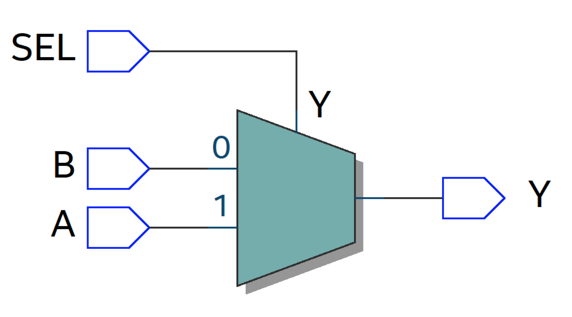
Fig. 2.21 Multiplexer#
For a combinational process all signals read by the process must be present in the sensitivity list. For the multiplexer example above, the signals A, B, and SEL are all read by the process. The wave diagram in figure Fig. 2.22 shows the expected behaviour of the multiplexer. As can be seen, the output Y follows the input B as long as SEL = ‘0’, otherwise it follows A.
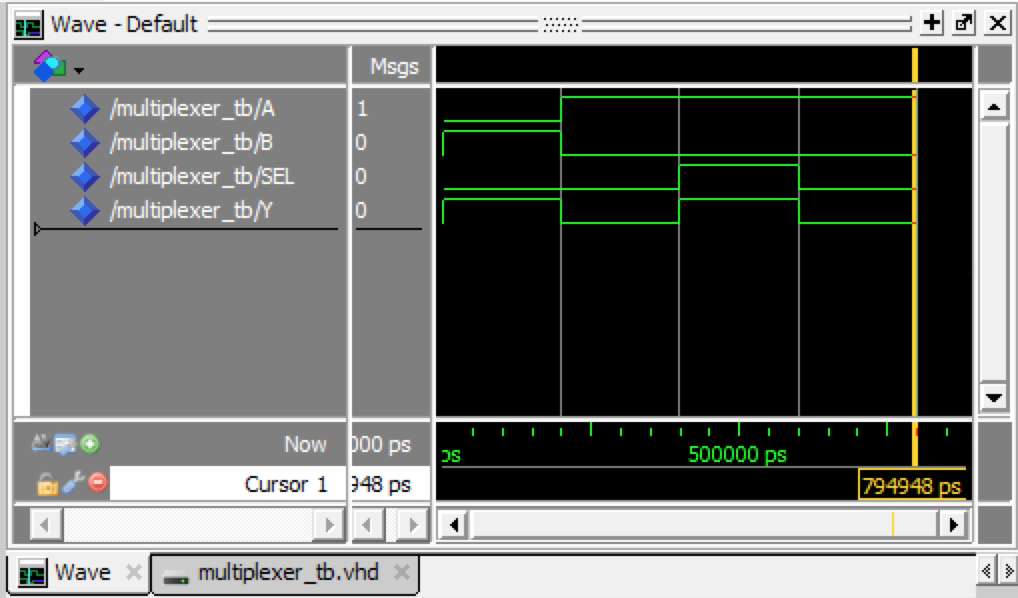
Fig. 2.22 Wave diagram for multiplexer#
2.10.4.1.1. Incomplete sensitivity list#
What would then happen in the case where a signal read by the process is not present in the sensitivity list? For the example below SEL is omitted from the sensitivity list.
process(A,B) is
begin
  if SEL = '1' then
    Y <= A;
  else
    Y <= B;
  end if;
end process
The simulation result show that the change in SEL no longer has an effect. When SEL changes, the input B is still feed to the output Y. As SEL is no longer in the sensitivity list, any changes on SEL will not trigger the process to run.
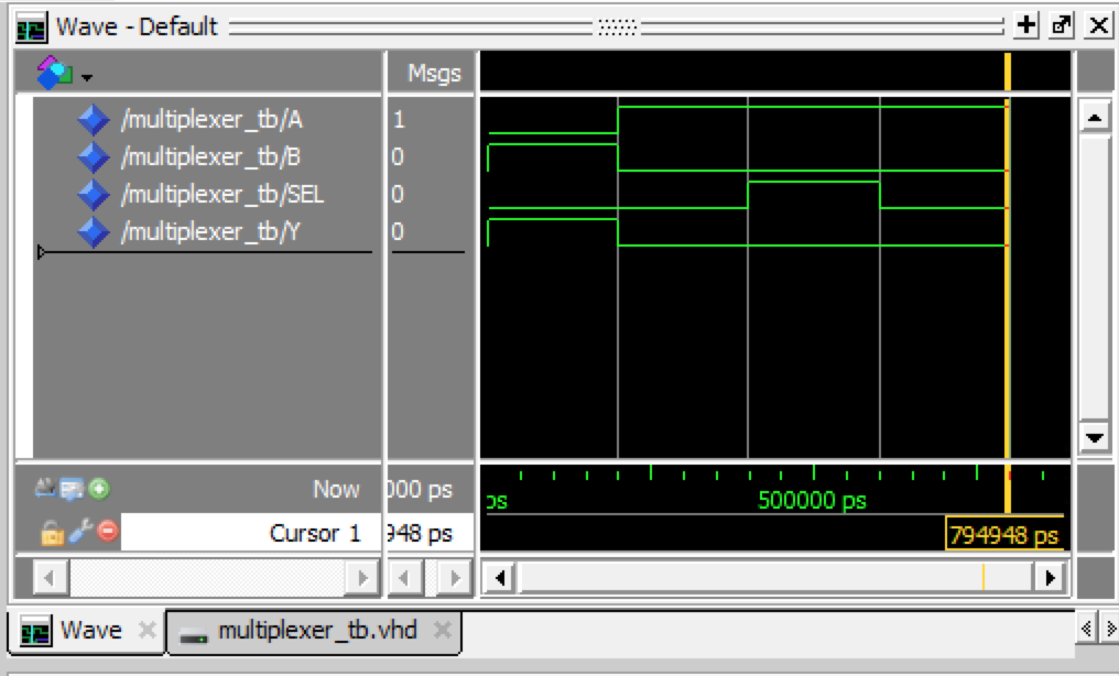
Fig. 2.23 Wave diagram for multiplexer where change occurs on the signal SEL which is omitted from the sensitivity list.#
However, if e.g. the signal B is changed, this triggers the process to run and the if-statement is re-evaluated, this time feeding through the value of A to the output.
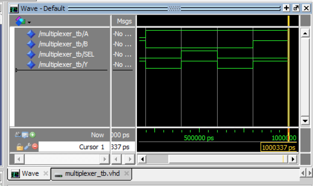
Fig. 2.24 Wave diagram for multiplexer where a change occurs on the signal B and where the signal SEL is omitted from the sensitivity list.#
2.10.4.1.2. Avoid unintentional latches#
Another common problem when writing combinational processes or non-clocked process is to forget to assign an ouput value for all possible paths through the logic. In this case the synthesis tool will assume that you want to use the previous value. #to not make sure that all possible paths will assign a value to the ouput.
In the example below the input SEL to the process is a 2-bit vector that can take 4 values: “00”, “01”, “10”, and “11”.
-- SEL is defined as std_logic_vector(1 downto 0)
process(A,B,SEL) is
begin
  if SEL = "00" then
    Y <= A;
  elsif SEL = "01"
    Y <= B;
  end if;
end process
When synthesizing this VHDL description in Quartus the following Warning is listed:
Warning (10631): VHDL Process Statement warning at multiplexer.vhd(18):
inferring latch(es) for signal or variable "Y", which holds its previous
value in one or more paths through the process
In the process above, the output Y is not determined for all possible values of the input SEL. E.g., when SEL=”10” or SEL=”11” the synthesizer does not know which value to assign to Y. Instead a latch is inferred to keep the previous value. The inferred logic which is shown in figure Fig. 2.25 can be generated by opening the RTL viewer in Quartus (Tools -> Netlist viewers -> RTL viewer)
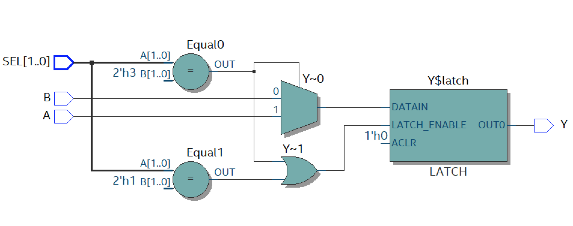
Fig. 2.25 Inferred latch.#
If you have not specified what the output should be for every possible set of input values, the option taken by VHDL is to not change the current output. A latch adds an extra path for the signal to travel and may impact the timing closure of the design. To avoid this make sure to assign a value to the output for all possible values of the inputs read by the process as shown below.
-- SEL is defined as std_logic_vector(1 downto 0)
process(A,B,SEL) is
begin
  if SEL = "00" then
    Y <= A;
  elsif SEL = "01"
    Y <= B;
  else
    Y <= A;
  end if;
end process
or using a default value
process(A,B,SEL) is
begin
  Y <= A; -- assign A as a default value
  if SEL = "00" then
    Y <= A;
  elsif SEL = "01"
    Y <= B;
  end if;
end process
The inferred logic will now be combinational only and without any memory element as seen in figure Fig. 2.26.
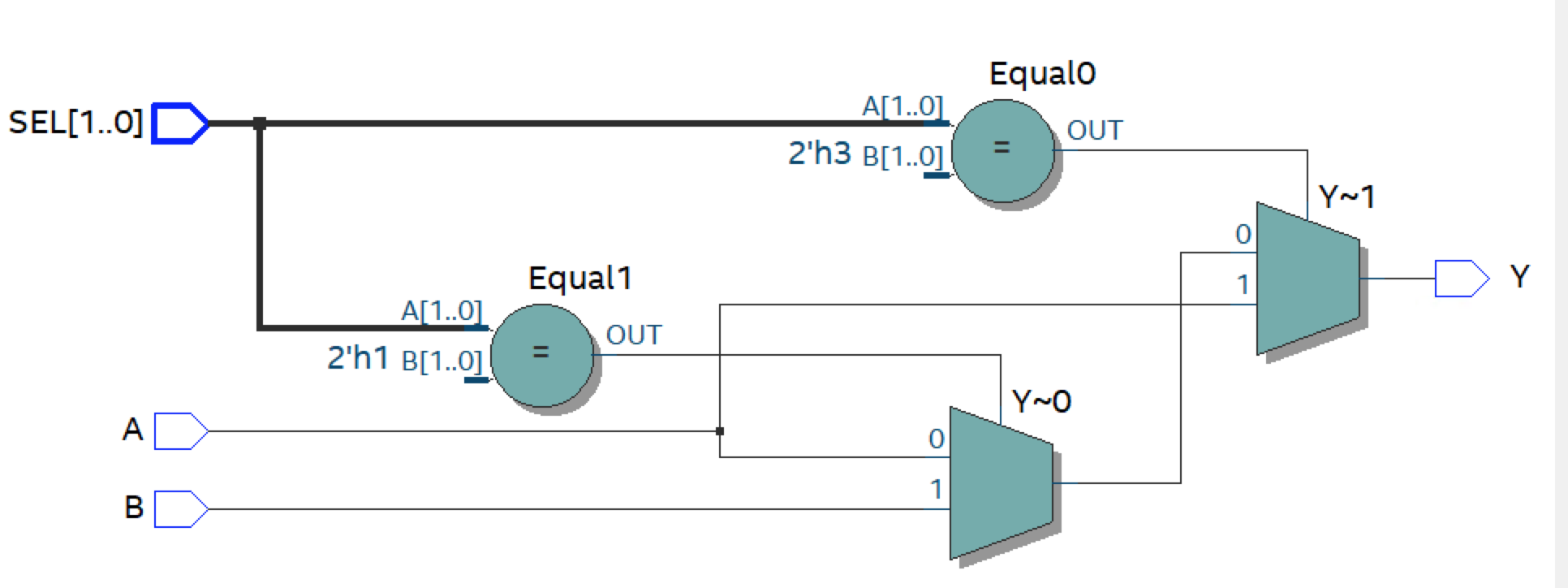
Fig. 2.26 A purely combinational results.#
For the second process above using a default assignment to Y, the order of the statements are important. While a process statement itself is concurrent, the statments within a process is read and evaluated sequentially. For multiple assignments to the same output signal, only the last assignment will be valid. For the example shown below, this means that A will always be assigned to Y, and the if-sentence will have no effect.
process(A,B,SEL) is
begin
  if SEL = "00" then
    Y <= A;
  elsif SEL = "01"
    Y <= B;
  end if;
  Y <= A;
end process
The corresponding RTL viewer output is shown in figure Fig. 2.27.
Fig. 2.27 Only the last statement in the VHDL description will be implemented.#
2.10.4.2. Synchronous process#
In VHDL a storage element can be implemented by making a process synchronous to the a clock. This is nothing else than a edge sensitive storing device, or D flip-flop.
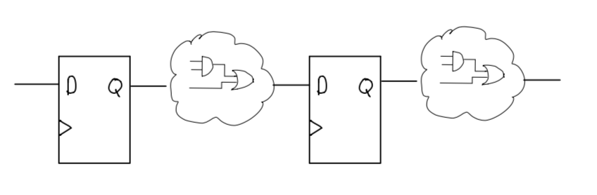
Fig. 2.28 Example where to D-flip-flops have been generated with logic in the path between them.#
A synchronous process is a clocked process
A synchronous process is activated only on a clock transition
Input data must be stable at start of process
A synchronous proecess will always result in a storage element for all signals which are assigned a value in the process
The most basic synchronous process without any reset is shown below:
p_reg: process(clk) is
begin
  -- do not write anything here
  if rising_edge(clk) then
    -- your logic is described solely within the rising_edge(clk)
    Y <= A;
  end if;
  -- do not write anything here
end process;
The implied storage capability is a result of not providing a condition that indicates what should happen if the listed if condition is not met. In other words, if the if condition is not met, the device does not change the value of Y and therefore it must remember the current value. When synthesized in Quartus this generates the following logic:
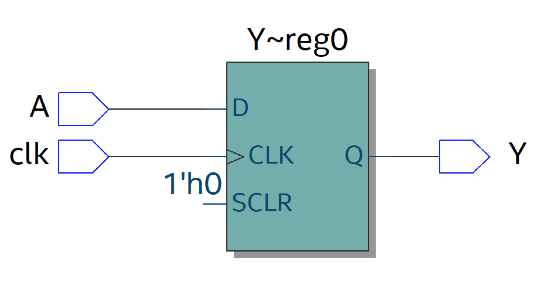
Fig. 2.29 Inferred register.#
Sensitivity list: For a synchronous process, only the clock signal shall be present in the sensitivity list, unless the process has an asynchronous reset.
2.10.4.2.1. Reset of synchronous processes#
A synchronous process can be reset using either
a synchronous reset signal
or an asynchronous reset signals
Asynchronous reset:
p_reg: process(clk, areset) is
begin
  -- do not write anything here
  if areset = '1' then
    Y <= '0';
  elsif rising_edge(clk) then
    Y <= A;
  end if;
  -- do not write anything here
end process;
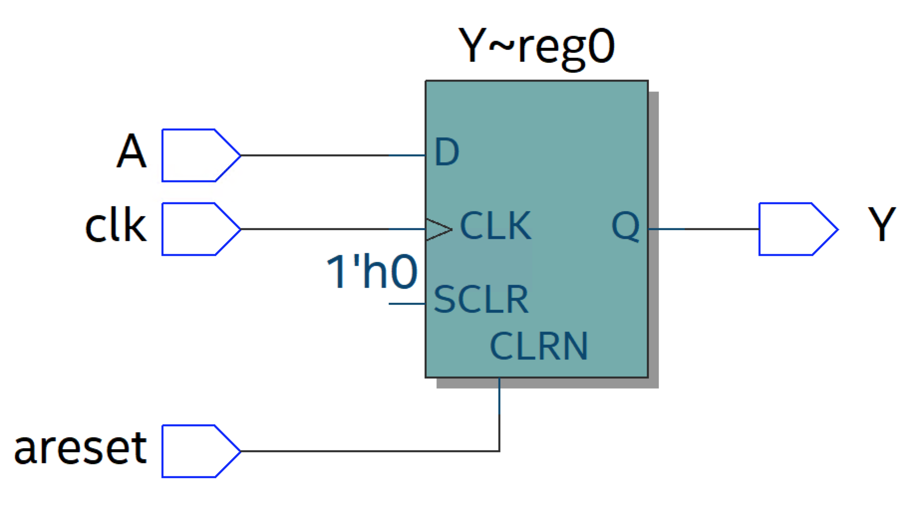
Fig. 2.30 Inferred register with asynchronous reset.#
Synchronous reset:
p_reg: process(clk) is
begin
  -- do not write anything here
  if rising_edge(clk) then
    if reset = '1' then
      Y <= '0';
    else
      Y <= A;
  end if;
  -- do not write anything here
end process;
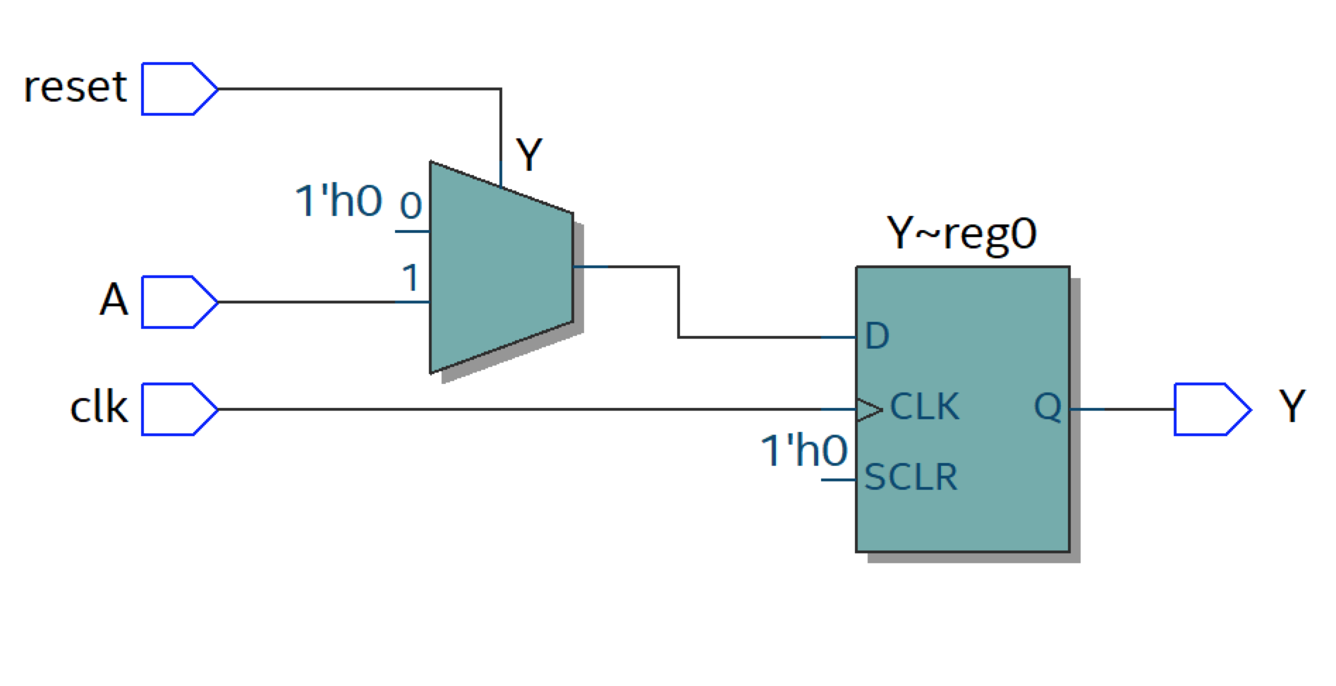
Fig. 2.31 Register with synchronous reset. In this case separate reset logic is inferred.#
2.10.4.2.2. Synchronous process with enable#
p_reg: process(clk) is
begin
  -- do not write anything here
  if rising_edge(clk) then
    if enable = '1' then
      Y <= A;
    end if;
  end if;
  -- do not write anything here
end process;
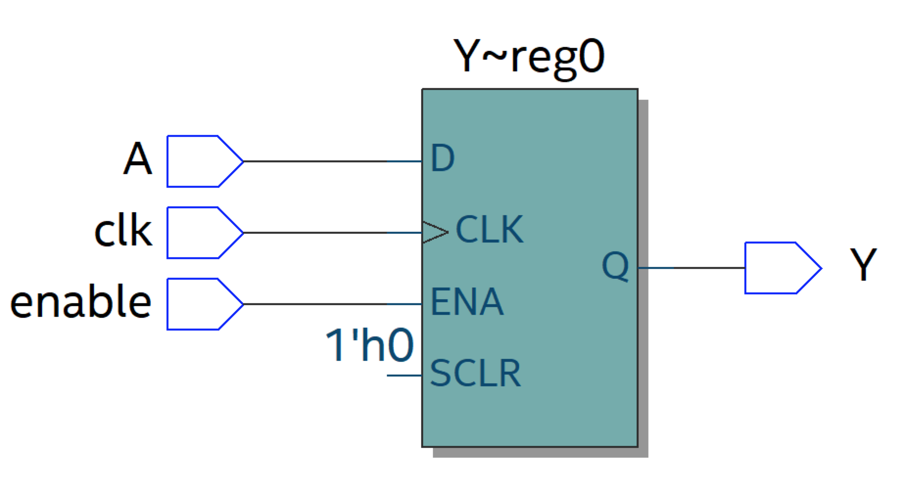
Fig. 2.32 Inferred register with enable#
2.10.5. Combining synchronous and combinational logic#
A general rule of thumb is that all signal assignments within a synchronous process will lead to the generation of a register (D flip-flop). If we take the example of the multiplexer and enclose it within a synchronous process making it dependent on the clock, a register will be added to the output.
process(clk) is
begin
  if rising_edge(clk) then
    if SEL = '1' then
      Y <= A;
    else
      Y <= B;
    end if;
  end if;
end process
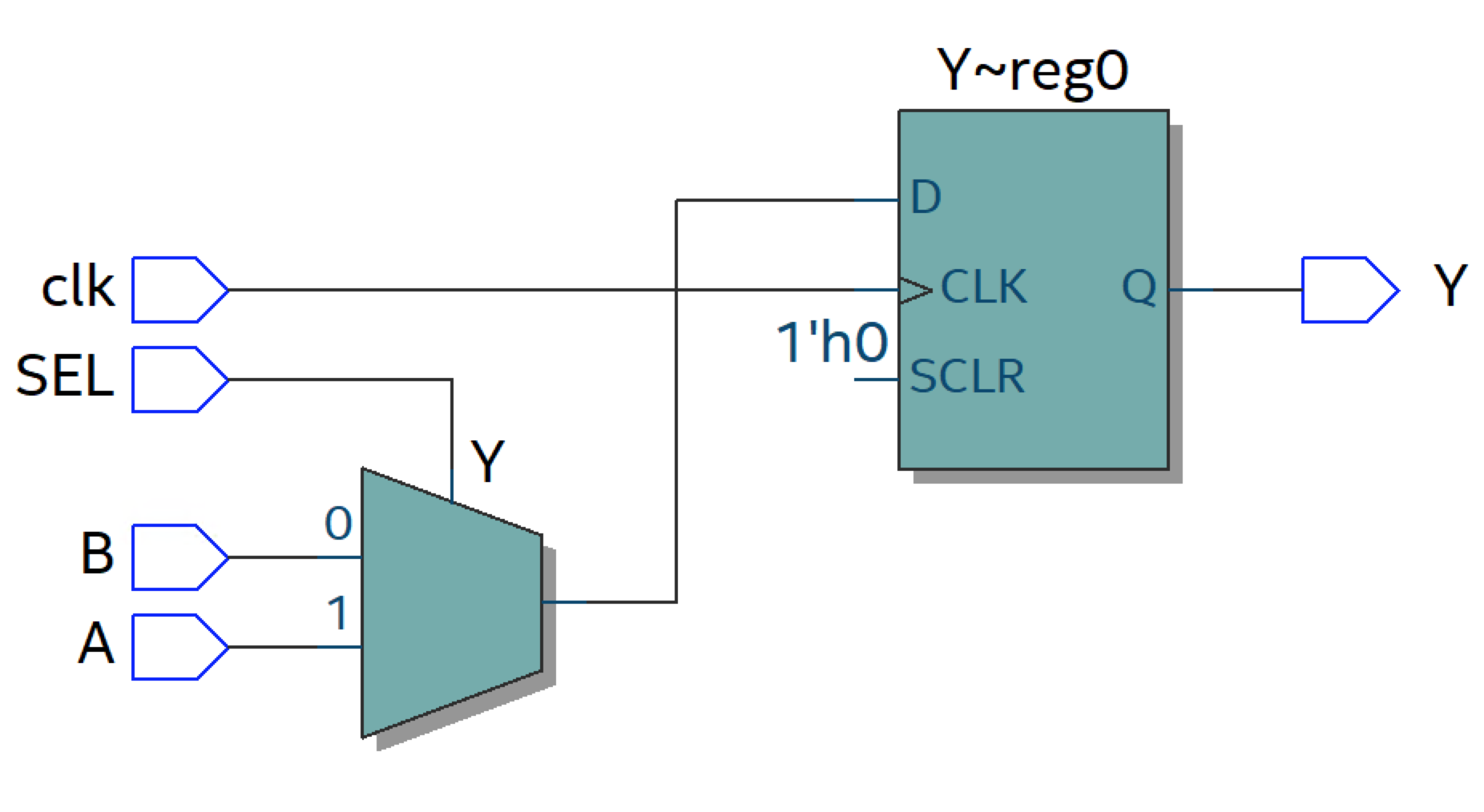
Fig. 2.33 Combinational and synchronous logic.#
2.10.6. Design with multiple processes#
As mentioned earlier, the process statement is itself a concurrent statement; and multiple process statements can be written in the same architecture.
architecture rtl of more_complex_design is

begin

proc1: process(clk)
begin
  if rising_edge(clk) then
  -- put your synchronous logic here
  end if;
end process;

-- A second synchronous process
proc2: process(clk)
begin
  if rising_edge(clk)
  -- put your other synchronous logic here
  end if;
end process;

-- A combinational process
proc3: process(signal1, signal2)
begin
-- put your combinational logic here
end process;

-- You can also add separate dataflow statements in the same architecture.
Y <= A and B;


end architecture;
For example, you could consider splitting the combinational and synchronous part of the design in Fig. 2.33 into two processes. The result will be exactly the same.
architecture rtl of multiple_process_example is

  signal Y_i : std_logic;

begin

-- Combinational process that will output
-- either A or B depending on the value of the select signal SEL
p_comb_mult: process(A,B,SEL) is
begin
  if SEL = '1' then
      Y_i <= A;
    else
      Y_i <= B;
    end if;
end;

-- Add a register on the output of the multiplexer to keep the value
-- stable for a clock cycle.
p_synch_reg: process(clk) is
begin
  if rising_edge(clk) then
    Y <= Y_i;
  end if;
end process
This is of course a very simple example. However, as your design becomes more complex, it is recommended to think about how you can partition your design into multiple processes or even entities/modules, according to their different functionalities and purposes. This will reduce the complexity of each process or module, which in turn will make it easier to write the VHDL description for the smaller unit of functionality, and improve readability. You will gain some experience with how to partition a design when you will write a basic UART controller in the first part of the project in this course: P1: UART controller.
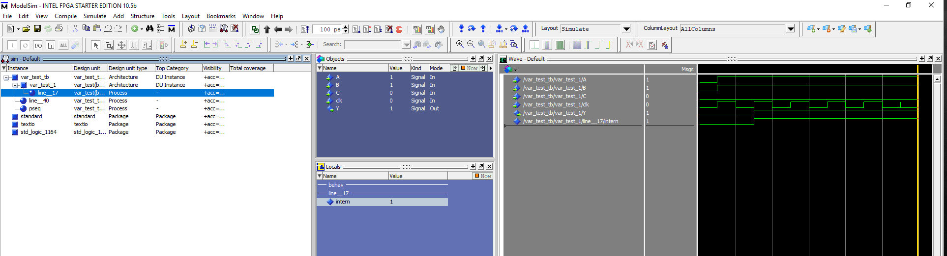
2.10.7. Finding the process internal variables in Modelsim#
The process below uses a variable internal to the process. If you would like to add this variable to the wave view in Modelsim, it is not located in the Objects window where you can find the signals but in a different window called Locals.
proc_var: process(clk) is
 variable intern : std_logic;
begin
 if rising_edge(clk) then
   intern := A and B;
   Y      <= intern or C;
 end if;
end process;
The Locals window can be opened through the View tab in the menubar as shown below.
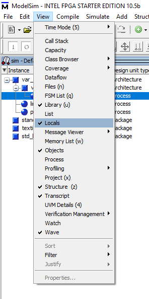
At first you will not see any local variables unless you have marked the relevant process in the Sim default window. It will then look like the figure below.
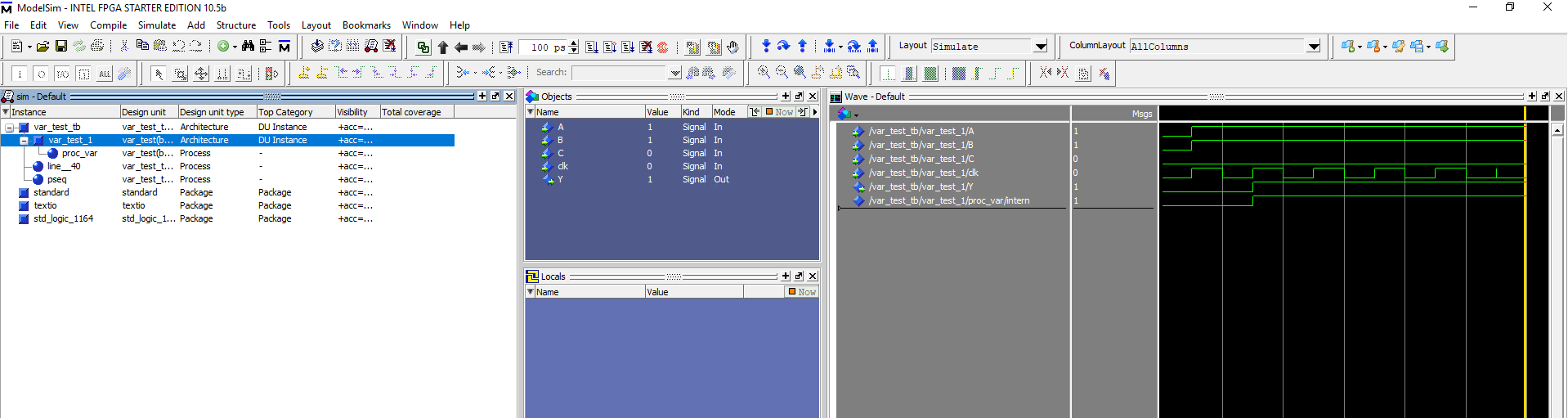
To view the internal variables of a process, mark the relevant process and you should see the variable listed as shown below.
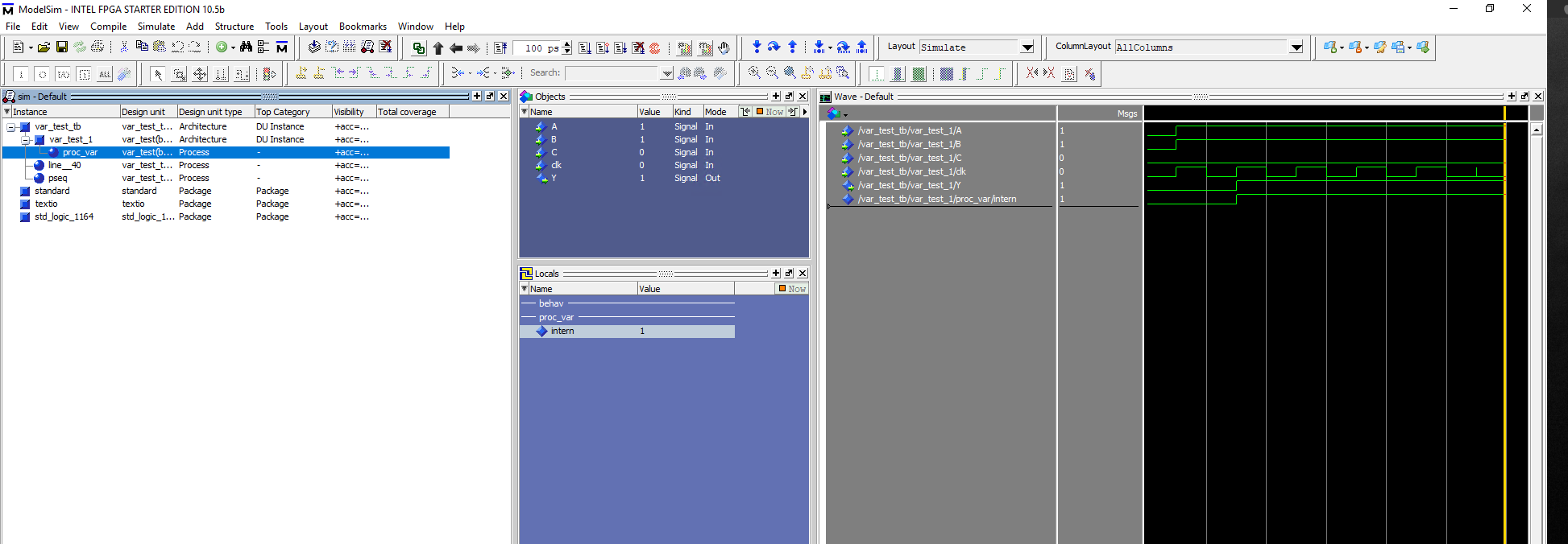
Here you can also see the process label which help you to identify the process you are looking for. The figure below shows how the process would be labelled if you do not give it a specific name. The process now has the unrecognizable label line__17.