P3: RTOS#
In this part of the embedded system project you will build the final software application to read out accelerometer sensor data and present this data on the host PC. The software application running on the microcontroller system will use a real-time operating system kernel to split the required functionality into smaller units (tasks), and intertask communication services to communicate data between tasks.
Preparation
Before you start, work through the example described in EX8: A basic RTOS application and EX9: Semaphore example.
These examples will provide you with the basics of how to write a uC/OS-II software application.
You should also study the datasheet of the ADXL345 [Devb], and in particular the sections:
Theory of operation (p. 13–14)
Serial communication (p. 15–22)
Register map (p. 23–27)
Tasks#
The main tasks of the software application is to:
Correctly configure the ADXL345 accelerometer.
Read out the X-, Y-, Z-data regsiters of the ADXL345.
Send the accelerometer data over the UART to the host PC.
The configuration will only be performed once at the start of the program, while the readout of data will be performed continuously. Reading data from the accelerometer and writing data to the UART are two operations that naturally can be split into two different tasks. These two tasks will be linked by a message sent from the accelerometer read tasks to the uart send task that contains a new packet of accelerometer data, see Fig. 85.
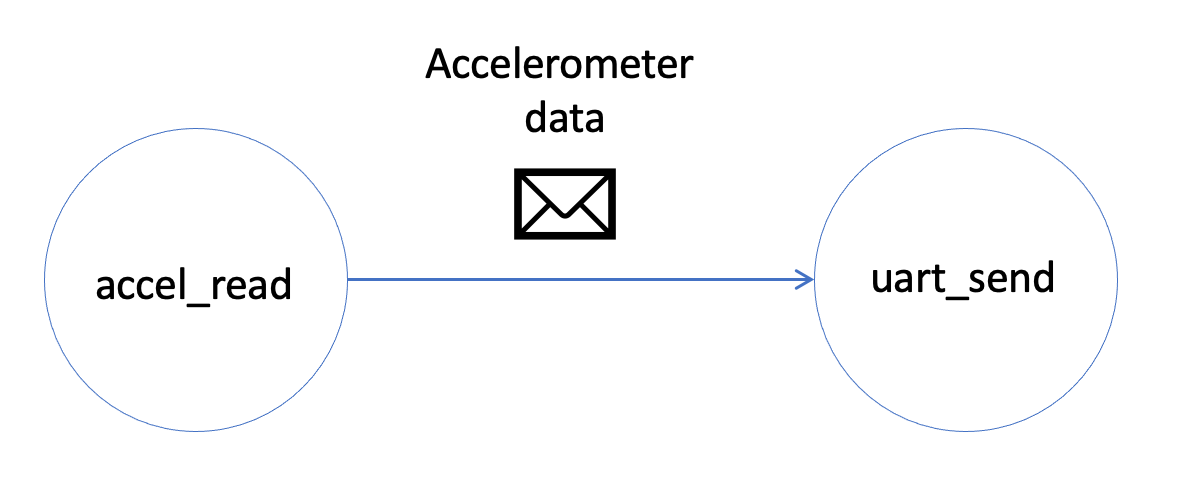
Fig. 85 One tasks reads data from the accelerometer and sends the data to another tasks that which again sends the data over the UART to the host PC.#
Data rates#
A packet of accelerometer data consist of X-, Y-, and Z-values, each two bytes in size.
For continuous operation the data rate is limited by the baudrate of the UART interface and the time it takes to execute the UART send command in the software. The time it takes to send it a data packet over the UART interface is:
# #bit = 8 data bits + 1 start bit + 1 stop bit
no_bytes = 6
no_bits_per_byte = 2 + 8
baudrate = 115200
time_byte = (no_bits_per_byte) * 1/baudrate
time_packet = time_byte * no_bytes
print("Time to send 1 byte UART: {:.1f} us".format(time_byte*1e6))
print("Time to send a data packet over the UART: {:.1f} us or {:.1} ms".format(time_packet*1e6,time_packet*1e3))
Time to send 1 byte UART: 86.8 us
Time to send a data packet over the UART: 520.8 us or 0.5 ms
This does not take into account the overhead of receiving the message from the accelerometer read task and executing the IOWR function to write to the TX data register of the UART. However, it sets an upper limit for the data rate.
The maxium SPI clock frequency for the ADXL345 is 5 MHz according to Table 10. on page 17 in the ADXL345 datasheet. However, the SPI IP core was configured to run at 1 MHz when included in the microcontroller system in Add an SPI module. When using the multi-byte mode of the SPI interface, one byte is first sent to the ADXL345 module before it returns the number of specified bytes. The time it takes to read out 6 data registers is:
spi_freq = 1e6 # Hz
no_bytes = 1 + 6
no_bits_per_byte = 8
time_packet = (no_bits_per_byte * no_bytes) * 1/spi_freq
print("Time to read a data packet form ADXL345: {:.1f} us".format(time_packet*1e6))
Time to read a data packet form ADXL345: 56.0 us
This is clearly faster than it takes to send the same data packet over the UART to the host PC. However, the output data rate of the ADXL345 is limited by the data rate of the interal ADC. According to Table 7. on page 14 in the ADXL345 datasheet[Devb], the maximum output data rate is 3200 Hz. This means that the data registers of the ADXL345 are updated every 0.3 millisecond. This is still faster than UART interface.
On page 15 of the datasheet, it is also stated that the use of the 3200 Hz and 1600 Hz output data rates is only recommended with SPI communication rates greater than or equal to 2 MHz. The 800 Hz output data rate is recommended only for communication speeds greater than or equal to 400 kHz, and the remaining data rates scale proportionally. With the current configuration of the SPI IP core, 800 Hz is therefore the maximum possible output data rate. This means that the data is updated every 1.25 milliseconds, which is 0.75 milliseconds slower than the UART interface. This may be OK, but to set a safety margin during the development, it is recommended to start at a lower output data rate, e.g., 100 Hz. The data will then be updated every 10 milliseconds. According to the overview of the register map in Table 19. this is also the default rate.
Interrupts and data flow#
The flow of data will be controlled using interrupts. An overview of the final solution is shown in Fig. 86. Since both the SPI and UART interfaces are accessed by one single task respectively, there is no need to use a protection semaphore for these resources.
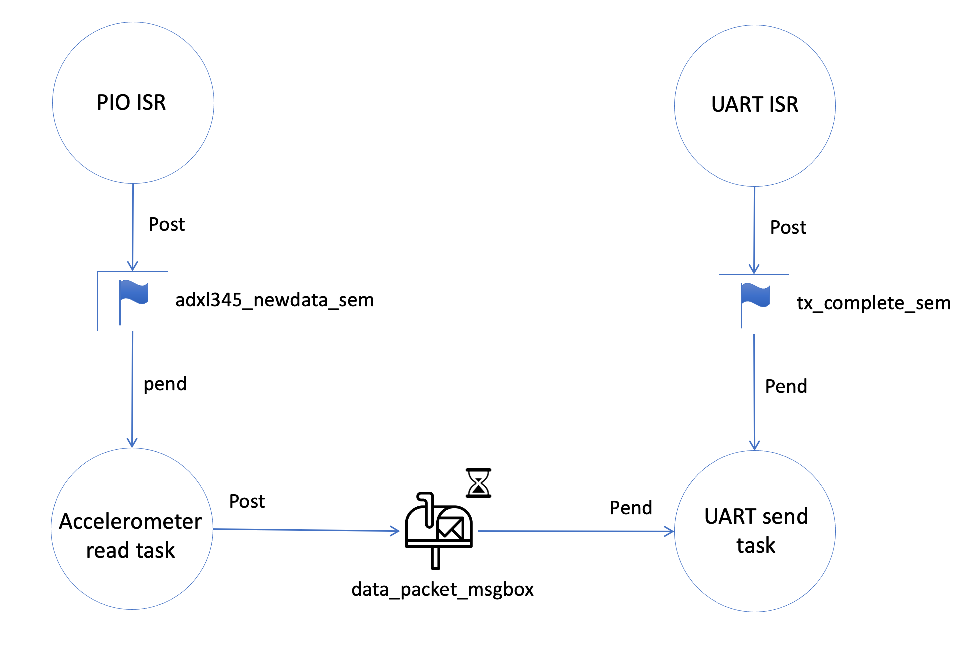
Fig. 86 An overview of how the tasks and interrupt service routines (ISR) communicate with synchronization semaphores and messages.#
Accelerometer read task#
The ADXL345 can be configured to provide an interrupt when new data is available in its data registers. The interrupt functionality is configured through the following registers:
INT_MAP: decides which interrupts goes to which interrupt pin
INT_ENABLE: enables the various interrupts
DATA_FORMAT: The INT_INVERT bit sets the polarity of the interrupt
The ADXL345 default interrupt polarity is active high. Since PIO module of the microcontroller system is configured to signal an interrupt on the falling edge of the input, the interrupt polarity of the ADXL345 must be set active low.
Configure the ADXL345 to signal a data ready interrupt on the INT2 pin.
A separate interrupt handling routine for the PIO interrupts must be written to detect the interrupt from the ADXL345. When the interrupt is detected, a semaphore must be used to signal that new data is available. The accelerometer read task waits (Pends) for this semaphore and performs a multi-byte (6 bytes) SPI read command to read the 6 data registers.
Important
The ADXL345 will generate an DATA_READY interrupt when new data has been made available in the respective data registers. However, the interrupt condition will only be cleared by reading the data registers. It is therefore recommended to clear any initial possible interrupt conditions that may be present before entering into the while loop of the accelerometer read task.
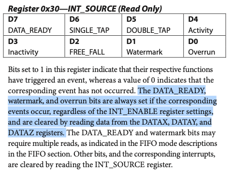
Fig. 87 The INT_SOURCE register where the DATA_READY bit will be set when new data is available in the data registers. This bit is reset when reading the data registers.#
Intertask message#
When new data has been read by the accelerometer read task, a \(\mu\)C/OS-II message mailbox will be used to send (Post) the new data to the UART send task. The message that will be sent is a pointer to a 6 byte array.
Tip
It is recommended that a multiple-byte read of all data registers is performed to prevent a change in data between reads of sequential registers. If the multiple-byte bit (MB) is hight, after the register addressing (command byte) and the first byte of data, each subsequent set of clock pulses (eight clock pulses) causes the ADXL345 to point ot the next register for a read or write. This shifting continues until the clock pulses cease and chips select is deasserted. To perform reads or writes on different, nonsequential registers, chip select must be deasserted between transmissions and the new register must be addressed separately.
spi_tx[0] = 0xc0 | 0x32; //multiple-byte read + address of first data register.
return_code = alt_avalon_spi_command(SPI_BASE,0,1,spi_tx,6,spi_rx,0);
The values from the 6 data register will now be available in the spi_rx array. The address of the first position of the array can now be posted to the mailbox.
// Post pointer to msgbox_buffer
error_code = OSMboxPost(data_packet_msgbox,(void*)spi_rx);
UART send task#
When sending data over the UART, the UART module will be busy for 86 microseconds and will not accept more than one new data byte during this period. From P1: UART controller, we know that the UART module will provide an interrupt when a transaction on either the TX or RX line is complete. You can use this interrupt to control flow of data to the UART module.
Tip
When a new data packet of 6 bytes has been received by the UART send task, each byte has to be written separately to the TX data register of the UART module. For each write transactions, the UART send task must wait (Pend) for a semaphore set by an interrupt handling routine. When a TX transaction is complete, the UART module will signal an interrupt to the CPU. The interrupt handling routine must then read the status register – if the TX IRQ bit is set, the semaphore is posted.
The data will be received through a message mailbox as a pointer to a 6 byte array. You must therefore loop through the array.
When receiving the data on the host PC it may be difficult to distinguish the the data packets from each other unless a packet header is added to the data. A simple solution can be to add a fixed byte in the first position of the array that can easily be recognized by the receiving software on the host PC.
alt_u8 data[8] = {0xe2,0,0,0,0,0,0,0};
It may also be desirable to add a packet counter as the next byte. This can e.g., be used to verify that all bytes have been received.
while (1)
  {
    //Get pointer to data from ADXL345
    data_ptr = (alt_u8*) OSMboxPend(data_packet_msgbox, 0, &error_code);
    // Increase sample counter and add to second byte of array.
    sample_counter++;
    data[1] = sample_counter;
    // Looping through the 6 bytes and sending over the UART
    // will take some time. Copy data to local array to avoid overwriting from the accelerometer task.
    for(int i=0; i<6; i++){
      data[i+2] = *data_ptr;
      data_ptr++;
     }
    // Send bytes over UART and wait for TX complete semaphore for each byte transaction.
    for(int i=0; i<8; i++){
       IOWR(UART_BASIC_BASE,0,data[i]);
       OSSemPend(tx_complete_sem, 0, &error_code);
    }
ADXL345 configuration#
In addition to configuring the ADXL345 interrupt behaviour, the required output data rate, resolution and range must also be considered. These settings are controlled by writing to the following registers:
BW_RATE
DATA_FORMAT
Since the default output rate of the ADXL345 is 100 Hz, there is no need to write configure the BW_RATE register unless you would like to try and run at a higher data rate.
To set the desired resolution and accelerometer range, you will have to set the corresponding bits of the DATA_FORMAT register. Notice that the INT_INVERT bit is also part of the DATA_FORMAT register.
Finally the POWER_CTL register must be considered to but the ADXL345 into a measure mode. To activate the ADXL345 the measure bit must be set to 1.
The configuration of the ADXL345 must be performed on startup before entering into the while loop of the accelerometer read task.
Host PC software#
The Python script below can be used to read the data from sent to the serial port on the host PC. It assumes that the data is right justified (justify-bit in DATA_FORMAT set to 0), and you will have to modify the RESOLUTION and RANGE parameters according to how you have configured the DATA_FORMAT register. It also assumes that the data packet sent from the microcontroller system consists of 8 bytes: one ID byte (0xe2), one packet counter byte, 6 data bytes.
The script requires the packages Pyserial and and numpy to be installed:
pip install pyserial numpy
Python script for reading the serial port and printing accelerometer data to the terminal:
import threading
import serial #pyserial: https://pyserial.readthedocs.io/en/latest/
import queue
import time
import numpy as np

# Modify RESOLUTION, RANGE and COM port according to your setting.
RESOLUTION = "FULL" # 10BIT
RANGE = 2 # 4/8/16
COM_PORT = "COM4" # Change according to the port which is used in your case


HEADER_ID = 0xe2
RESOLUTION_TABLE = {"FULL":{2:2/2**9,4:4/2**10,8:8/2**11,16:16/2**12},
              "10BIT":{2:2/2**9,4:4/2**9,8:8/2**9,16:16/2**9}}

# Create a command queue for key
cmd_queue = queue.Queue(10)

# Keyboard thread to detect input commands and put them in the command queue
def keyboard(run_app):
    while run_app():
        cmd = input("\r\n> ")
        cmd_queue.put(cmd)
        time.sleep(0.5)


# Keep program running as long as True. Terminate by writing "quit" in terminal window
run_app = True

# Thread for reading serial data
def serial_data(run_app):
    # Open serial port
    ser = serial.Serial(COM_PORT, 115200,timeout = 1)

    # Initialize a data packet array with zero data bytes
    data_packet = bytearray(0)
    # Initalize a data packet window array to shift through the data bytes.
    # This window will be used to find the start of the data packet, and when
    # a full packet has been received, copy the data packet to the data_packet array.
    packet_window = bytearray(0)

    new_packet = False
    packet_cnt = 0

    while run_app():

        no_bytes = ser.inWaiting()
        if no_bytes > 0:
            data = ser.read(no_bytes)

            # Loop through received bytes
            for byte_value in data:
                # Add received byte to the packet window
                packet_window.append(byte_value)
                # Find index of header id
                start_idx = packet_window.find(HEADER_ID)
                # If correct header ID is found in first position and a total of 9 bytes have been received
                # the packet window may no contain a full valid data packet.
                if start_idx == 0 and len(packet_window) == 9:
                    # check if last byte is start of next packet. If true, a full correct data packet has been received.
                    if packet_window[8] == HEADER_ID:
                        data_packet = packet_window[2:-1] # Extract the 6 data bytes
                        packet_no = int(packet_window[1]) # Extract the packet counter
                        new_packet = True
                        packet_cnt = packet_cnt + 1
                if new_packet: # New data packet is available, organize data bytes
                    new_packet = False

                    # The data is received in the following order
                    # x0, x1, y0, y1, z1, z2. This means that the least significatn byte is at the lowest position in the byte array
                    # corresponding to little endian. The data for each axis is 2 bytes or 16 bits which corresponds to a short.
                    # It is also formated in two-complement format, which means that it is a signed short.

                    # Arrange bytes
                    x_value_raw = (data_packet[1] << 8) +  data_packet[0]
                    y_value_raw = (data_packet[3] << 8) +  data_packet[2]
                    z_value_raw = (data_packet[5] << 8) +  data_packet[4]

                    # Convert to signed 16 bit
                    x_value = np.int16(x_value_raw)
                    y_value = np.int16(y_value_raw)
                    z_value = np.int16(z_value_raw)

                    # Convert to g
                    x_value = x_value * RESOLUTION_TABLE[RESOLUTION][RANGE]
                    y_value = y_value * RESOLUTION_TABLE[RESOLUTION][RANGE]
                    z_value = z_value * RESOLUTION_TABLE[RESOLUTION][RANGE]

                    # Print value in g
                    print("Packet no: {:3d}, (x: {:+1.3f}), (y: {:+1.3f}), (z: {:+1.3f})".format(packet_no, x_value, y_value, z_value))
                    # print raw value
                    # print("Packet no: {:3d}, (x:{:4x}), (y:{:4x}), (z:{:4x})".format(packet_no, x_value_raw, y_value_raw, z_value_raw))


                ## remove oldest received byte
                if len(packet_window) == 9:
                    packet_window.pop(0)
        time.sleep(0.001)

    ser.close()

if __name__ == "__main__":

    # Create threads
    keyboard_thread = threading.Thread(target=keyboard, args=(lambda: run_app,))
    serial_thread = threading.Thread(target=serial_data, args=(lambda: run_app,))

    # Set threads as deamon -- threads are automatically killed if program is killed
    # if you are using Python 3.10 the following two lines seems to give an error messages.
    # For now, just comment them out.
    # keyboard_thread.setDaemon(True)
    # serial_thread.setDaemon(True)

    # Start threads
    keyboard_thread.start()
    serial_thread.start()

    while run_app:
        while not cmd_queue.empty():
            cmd = cmd_queue.get()
            if "quit" == cmd.lower():
                run_app = False
        time.sleep(0.1)