2.5. Objects and data types#
2.5.1. Objects#
An object in VHDL is a named item that has a value of a specific type [Ash10]. The most important objects in VHDL are:
Signals
Variables
Constants
2.5.1.1. Signals#
A signal can be thought of as a wire or interconnection (real physical signal). Signals are most commonly declared in the declaration part of the architecture, for signals internal to the module; in the entity declaration for signals that are used to interface the module; in packages for signal declarations that are meant to be visible or reused in multiple modules. Port declarations are implicit signal declarations, and thus the keyword signal is omitted. A port declaration is visible in all architectures assigned to that entity. A signal is declared using the signal keyword, an identifier, a type, and an optional default value:
signal <identifier> : <type> [:= initial_value]
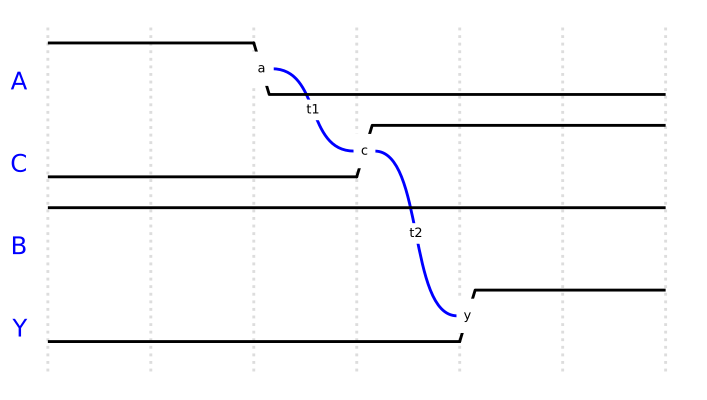
An example of an internally declared signal C is shown in Fig. 2.8. This example also demonstrates the concept of concurrent signal assignment in VHDL. Signal assignment in VHDL uses the operator “<=”. In this example the inverted value of A will be assigned to C, while the result of the operation B and C will be assigned to Y. These two lines are concurrent statements which both will be translated to hardware operating in parallel. In this case, an inverter operating on the input A in addition to an AND-gate with inputs B and C. If you consider that all gates are associated with a gate delay, that is, a change on the input needs to propagate through the logic gate and is therefore not instantaneously reflected on the output, you can maybe appreciate the fact that signal assignments are associated with a delay. Fig. 2.8 illustrates this case where a change on A is reflected on the output C after a time t1, and then the change on C is again reflected on the output Y after a time t2.
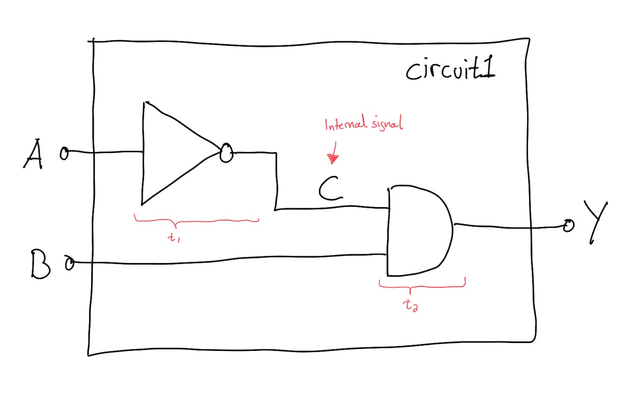
Fig. 2.8 Example ciruict with internal signal C.#
library ieee;
use ieee.std_logic_1164.all;

entity circuit1 is
  port(
    A : in std_logic;
    B : in std_logic;
    Y : out std_logic
    );

architecture func of circuit1 is

signal C : std_logic;

begin

-- Concurrent statements

C <= not A;
Y <= B and C;

end architecture;
2.5.1.2. Variable#
Variables are different from signals in that they do not represent a physical wire, but may be used for intermediate storage. Different from signals, assignments to variables are made instantaneously. Variables only exist within a VHDL process statement, which will be introduced later. A variable is declared in the declaration part of a process, before the begin statement. The declaration syntax is similar to that of signals:
variable <identifier> : <type> [:= initial_value]
2.5.1.3. Constants:#
Constants are useful objects for representing values that will not change and that will be used multiple times in a design. Constants can be declared in the declaration part of the architecture, in the entity declaration, and in a package. The declaration syntax is similar to that of signals and variables:
constant <identifier> : <type> [:= initial_value]
2.5.2. Data types#
The concept of type is very important in VHDL. The type of an object defines the set of values that the object can assume, as well as the set of operations that can be performed on those values [Ash10]. VHDL is said to be a strongly typed languages, meaning that an object can only be assigned values of the same type that was used to declare the object. The advantage of a strongly typed language is that errors will be detected at an early phase of the design process.
2.5.2.1. Commonly used types#
The two most commonly used types in VHDL are probably:
std_logic
std_logic_vector
The std_logic type was introduced in the IEEE std_logic_1164 standard to represent all logic values that can be modelled and synthesised in a modern programmable logic device. It can be thought of as representing a single wire or bit. A std_logic_vector is an efficient way of grouping together a set of signals with the same name, e.g. an 8-bit data bus.
In an electronic circuit logic values of 0 (low) and 1 (high) are represented by using voltages. E.g. 0 V for a logic low value and 1.2 V, 3.3 V or 5 V for a logic high value depending on the technology used. In VHDL these values can be represented by a std_logic value of ‘0’ or ‘1’.
Since std_logic can be use to represent synthesizable logic values, this is also the type that must be used on the top level entity of a design where the ports will connect to physical pins of the FPGA. For ports in entities that are internal to your system and will not be connected to FPGA pins, other types can also be used.
entity top_level is
  port (
    clk:  in  std_logic; -- Single line input line
    data: out std_logic_vector(7 downto 0)  -- 8-bit wide output line
     );
end entity top_level;
The type std_logic is also frequently used to declare signals internal to the architecture. An internal signal as declared in the example below, does not represent an inherent direction as when declared in the entity port declaration. The flow of data is decided by how the signal is connected in your design.
signal internal : std_logic;
signal data_internal : std_logic_vector(15 downto 0);
Since VHDL is a strongly typed languages, this means that not only the type but also the width has to match when connecting objects. If the width is different, a subset of a vector can be accessed as shown below. If the type is different, an appropriate type conversion is needed.
data_out <= data_internal(7 downto 0);
Other relevant types in VHDL are:
enumerated
boolean
integer
bit, bit_vector
std_ulogic
std_ulogic_vector
unsigned, signed
Of these, unsigned, integer, enumerated, boolean are the types that will be used in FYS4220.
2.5.2.2. std_ulogic#
As already introduced, the std_logic type is used to represent a synthesizable logic value or wire, and is defined in and available after the declaration of the VHDL package:
library ieee;
ieee.std_logic_1164.all;
In fact, std_logic is a subtype resolved of std_ulogic. In the IEEE-1164 package, std_logic is declared as shown below.
subtype std_logic is resolved STD_ULOGIC;
Where std_ulogic is declared as an enumerated type:
type std_ulogic is ( U', -- uninitialised,
                     'X', -- forcing unknown
                     '0', -- forcing 0
                     '1', -- forcing 1
                     'Z', -- high impedance
                     'W', -- weak unknown
                     'L', -- weak 0
                     'H', -- weak 1
                     '-'  -- unspecified (do not care)
);
This means that an object of type std_logic also can assume the values listed above. The value ‘U’ is the first of the listed values. That is reason for why a signal of the type std_logic or std_ulogic will get the value ‘U’ if you do not specify an initial value for the signal.
The list of enumerated values are due to the desire to model the more complex values that a digital signal can assume, e.g. tristate drivers, pull-up and pull-down outputs, high impedance state.
The IEEE-1164 library also defines functions for the various logic operations that can be applied to VHDL objects. E.g., it defines a function and that describes the result of the logical operation and between two objects. When these two objects are of the type std_ulogic and assume either of the values ‘0’ and ‘1’, the outcome can be defined. However, if any of the other values are assumed, the outcome of a logic operation will be undefined ‘U’ or forced into an unknown value ‘X’. For std_ulogic the result is decided by a resolution table that for an and operation is defined as shown below.
-- truth table for "and" function
 constant and_table : stdlogic_table := (
   --      ----------------------------------------------------
   --      |  U    X    0    1    Z    W    L    H    -         |   |
   --      ----------------------------------------------------
            ('U', 'U', '0', 'U', 'U', 'U', '0', 'U', 'U'),  -- | U |
            ('U', 'X', '0', 'X', 'X', 'X', '0', 'X', 'X'),  -- | X |
            ('0', '0', '0', '0', '0', '0', '0', '0', '0'),  -- | 0 |
            ('U', 'X', '0', '1', 'X', 'X', '0', '1', 'X'),  -- | 1 |
            ('U', 'X', '0', 'X', 'X', 'X', '0', 'X', 'X'),  -- | Z |
            ('U', 'X', '0', 'X', 'X', 'X', '0', 'X', 'X'),  -- | W |
            ('0', '0', '0', '0', '0', '0', '0', '0', '0'),  -- | L |
            ('U', 'X', '0', '1', 'X', 'X', '0', '1', 'X'),  -- | H |
            ('U', 'X', '0', 'X', 'X', 'X', '0', 'X', 'X')   -- | - |
            );
To resolve this, and to define an appropriate resolved value for all combinations of the values that an object of type std_ulogic can assume, the IEEE-1164 package introduces the type std_logic which is resolved subtype of std_ulogic. The resolved keyword means that a resolution function is applied to make sure that the value is resolved if there are multiple drivers. The applied resolution table is shown below.
-------------------------------------------------------------------
  -- resolution function
  -------------------------------------------------------------------
  constant resolution_table : stdlogic_table := (
    --      ---------------------------------------------------------
    --      |  U    X    0    1    Z    W    L    H    -        |   |
    --      ---------------------------------------------------------
             ('U', 'U', 'U', 'U', 'U', 'U', 'U', 'U', 'U'),  -- | U |
             ('U', 'X', 'X', 'X', 'X', 'X', 'X', 'X', 'X'),  -- | X |
             ('U', 'X', '0', 'X', '0', '0', '0', '0', 'X'),  -- | 0 |
             ('U', 'X', 'X', '1', '1', '1', '1', '1', 'X'),  -- | 1 |
             ('U', 'X', '0', '1', 'Z', 'W', 'L', 'H', 'X'),  -- | Z |
             ('U', 'X', '0', '1', 'W', 'W', 'W', 'W', 'X'),  -- | W |
             ('U', 'X', '0', '1', 'L', 'W', 'L', 'W', 'X'),  -- | L |
             ('U', 'X', '0', '1', 'H', 'W', 'W', 'H', 'X'),  -- | H |
             ('U', 'X', 'X', 'X', 'X', 'X', 'X', 'X', 'X')   -- | - |
             );
Supplementary suggested reading
Read more about objects and types in chapter 11 in Mealy and Teppero, Free Range VHDL.