2.13. State machines#
Finite state machines (FSMs) are used to solved many problems in digital electronics. An FSM is used to model a behaviour composed of a finit number of states, input events, transitions between those states (rules and conditions), and actions. That is, a state machine will read a series of inputs and switch to different states depending on the value of the inputs. Each state specifies which state to switch to for a given input value. A state machine is an effective method for implementing control functionality. In this course we will use it to implement the control state machine for the reciever and transmitter of a UART.
We have already seen how VHDL can be used to describe combinational and synchronous logic where the output only is dependent on the present value of the inputs as seen in Fig. 2.48.
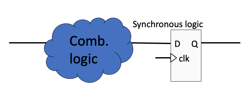
Fig. 2.48 Synchronous logic.#
However, if we add feedback to the system as seen in Fig. 2.49, the output becomes dependent not only on the present value of the system’s inputs but also on the sequence of past events. This is referred to as sequential logic.
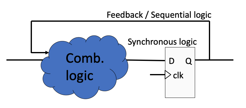
Fig. 2.49 Sequential logic.#
An FSM design is just a step beyond sequential: the hardware implementation requires a register to store the state value, a block of combinational logic to determine the state transition, and a block of combinational logic that determines the output of the FSM. These blocks are illustrated in figure Fig. 2.50. The current state is stored in registers and updated synchronous to the clock.
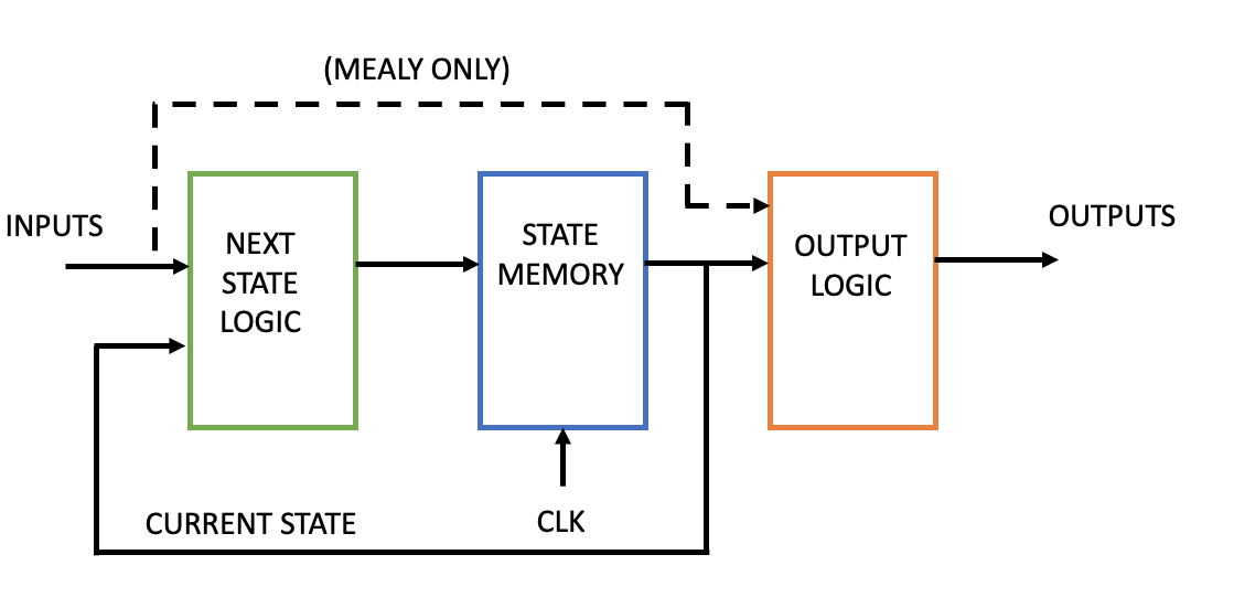
Fig. 2.50 State machine block diagram.#
There are two basic types of finite state machine behaviours: Moore and Mealy.
2.13.1. Moore#
In a Moore type state machine the outputs are a function of the current state only. This corresponds to Fig. 2.50 without the dashed line marked with (MEALY ONLY).
A state diagram of a Moore machine is shown in Fig. 2.51 where the circles represent the current state and the arrows represent the transitions between the different states. The labels inside the circles represent the name of the current state and the corresponding output value for that state. The label on the arrow represent the input condition that must be present for the transition to take place.
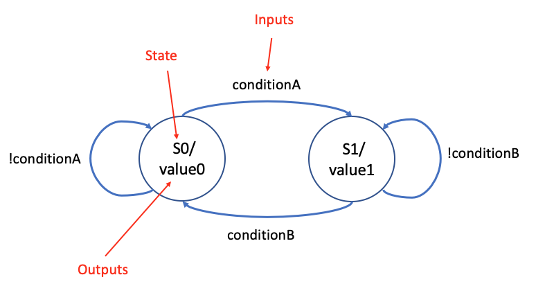
Fig. 2.51 Moore state diagram.#
2.13.2. Mealy#
In a Mealy type state machine the outputs are a function not only of the current state but also on all the inputs. This corresponds to Fig. 2.50 including the dashed line marked with (MEALY ONLY). Due to the direct dependence on the inputs, the ouputs of a Mealy machine works one clock cycle in advance of a Moore machine.
A state diagram of a Mealy machine is shown in Fig. 2.52 where the circles represent the current state and the arrows represent the transitions between the different states. Since the output of a Mealy machine is a function of both the current state and the inputs, the output label is associated with the transition arrows.
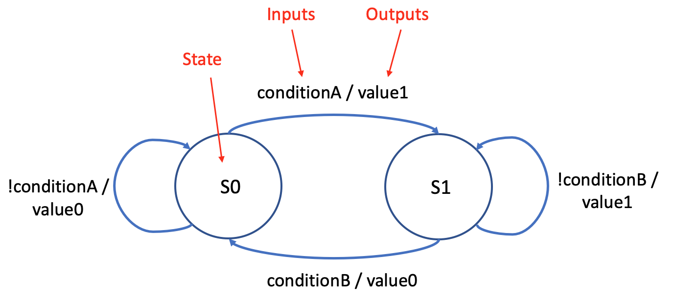
Fig. 2.52 Mealy state diagram.#
2.13.3. Design of FSMs in VHDL#
An FSM can be described in VHDL using different approaches. The following examples will show 3 common approaches. They differ mainly by how many process statements are used to describe the logic. An FSM can be implemented entirely in one single synchronous (clocked) process, or it can be split into one synchronous process and one or two combinational processes.
One Process FSM: Since the current state is stored in memory elements such as registers (flip flops), at least 1 synchronous process is needed to describe a state machine. This synchronous process will then include logic to determine the next state as a function of the inputs, update the current state, and determine the outputs value as a function of the current state (and the inputs for a Mealy machine).
Two process FSM: For a two process approach it is common to split the output logic into a separate combinational process. The synchronous process evaluates the inputs and calculates the next state value which then is updated on the next active clock edge.
Three process FSM: For a three process state machine both the input logic and ouput logic are described in separate combinational processes. The block diagram in figure Fig. 2.50 corresponds well to a three process state machine with one combinational process to calculate the next state, one synchronous process to update and store the current state, and one combinational process to determine the output values.
2.13.4. Declaration of states#
We make use of the enumerated data type in VHDL to declare the states. With this data type we can specify a list of legal values that a variable or signal of the defined type may be assigned. This enhances the readability when dealing with state machine descriptions. Instead of defining fixed bit patterns or values for each state, the symbolic names are automatically mapped to a bit level representation during synthesis. For the example shown in Fig. 2.53 and Fig. 2.54 we have three legal states S0, S1, and S2. A new type state_type is declared as an enumerated list of symbolic names. We can then declare a signal of this new type, which can be assigned the values specified in the list.
type state_type is (S0,S1,S2);
signal state : state_type;
We will demonstrate the one process, two process, and three process implementation using the Moore and Mealy state diagrams in Fig. 2.53 and Fig. 2.54.
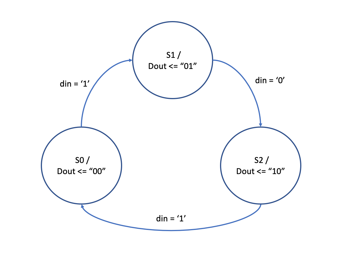
Fig. 2.53 Moore example state diagram.#
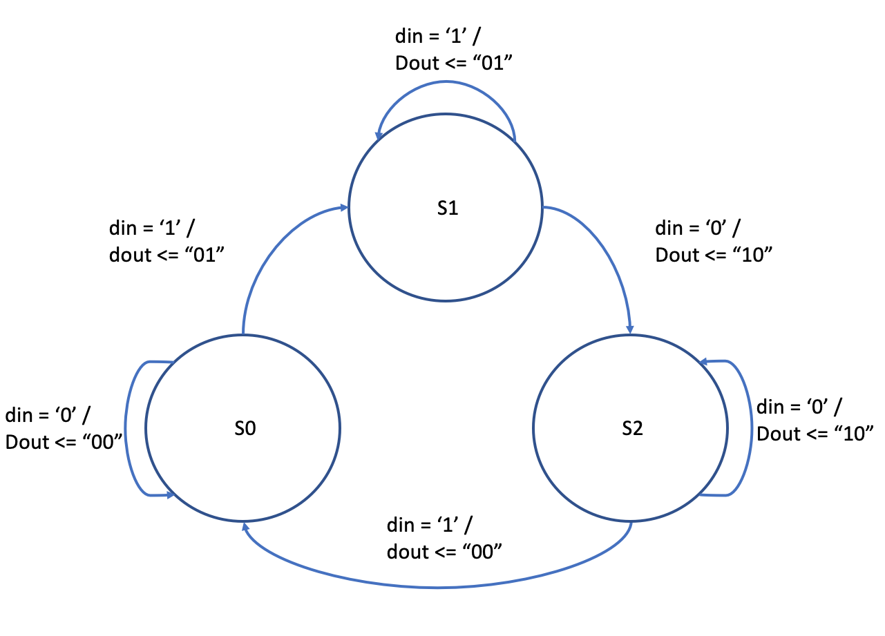
Fig. 2.54 Mealy example state diagram.#
Both examples have the entity declaration shown below.
entity statemachine is
  port(
    clk  : in  std_logic;
    din  : in  std_logic;
    dout : out std_logic_vector(1 downto 0)
    );
end entity;
2.13.5. One process state machine#
The one process state machine are commonly used for simple state machines and implements all the logic inside one synchronous process.
One process Moore
architecture moore_oneprocess of statemachine is

  type state_type is (S0, S1);
  signal state_moore : state_type;

begin

p_state : process(clk) is
begin
  if rising_edge(clk) then
    case state_moore is
      when S0 =>
        dout <= "00";
        if din = '1' then
          state_moore <= S1;
        end if;

      when S1 =>
        dout <= "01";
        if din = '0' then
          state_moore <= S2;
        end if;

      when S2 =>
        dout <= "10";
        if din = '1' then
          state_moore <= S0;
        end if;
    end case;
  end if;
end process;

end architecture;
One process Mealy
architecture mealy_oneprocess of statemachine is

  type state_type is (S0, S1);
  signal state_mealy : state_type;

begin

p_state : process(clk) is
begin
  if rising_edge(clk) then
    case state_mealy is
      when S0 =>
        if din = '1' then
          state_mealy <= S1;
          dout        <= "01";
        else
          dout <= "00";
        end if;
      when S1 =>
        if din = '0' then
          state_mealy <= S2;
          dout        <= "10";
        else
          dout <= "01";
        end if;
      when S2 =>
        if din = '1' then
          state_mealy <= S0;
          dout        <= "00";
            else
          dout <= "10";
        end if;
    end case;
  end if;
end process;

end architecture;
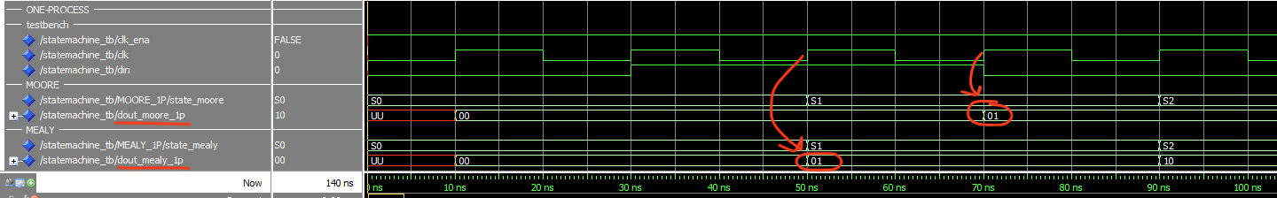
Fig. 2.55 Simulation result of a Moore and Mealy machine implemented using one synchronous process. Notice how the ouputs of the Mealy machine changes one clock cycle in advance of the Moore machine.#
2.13.6. Two process state machine#
For a two process approach it is common to split the output logic into a separate combinational process.
Two process Moore
architecture moore_twoprocess of statemachine is

  type state_type is (S0, S1, S2);
  signal state_moore : state_type;


begin

p_state : process(clk) is
begin
  if rising_edge(clk) then
    case state_moore is
      when S0 =>
        if din = '1' then
          state_moore <= S1;
        end if;
      when S1 =>
        if din = '0' then
          state_moore <= S2;
        end if;
      when S2 =>
        if din = '1' then
          state_moore <= S0;
        end if;
    end case;
  end if;
end process;

p_comb_out : process(state_moore) is
begin
  case state_moore is
    when S0 =>
      dout <= "00";
    when S1 =>
      dout <= "01";
    when S2 =>
      dout <= "10";
  end case;
end process;

end architecture;
Two process Mealy
architecture mealy_twoprocess of statemachine is

  type state_type is (S0, S1, S2);
  signal state_mealy : state_type;


begin

p_state : process(clk) is
begin
  if rising_edge(clk) then
    case state_mealy is
      when S0 =>
        if din = '1' then
          state_mealy <= S1;
        end if;
      when S1 =>
        if din = '0' then
          state_mealy <= S2;
        end if;
      when S2 =>
        if din = '1' then
          state_mealy <= S0;
        end if;
    end case;
  end if;
end process;


p_comb_out : process(state_mealy, din) is
begin
  case state_mealy is
    when S0 =>
      if din = '1' then
        dout <= "01";
      else
        dout <= "00";
      end if;
    when S1 =>
      if din = '0' then
        dout <= "10";
      else
        dout <= "01";
      end if;
      when S2 =>
      if din = '1' then
        dout <= "00";
      else
        dout <= "10";
      end if;
  end case;
end process;

end architecture;
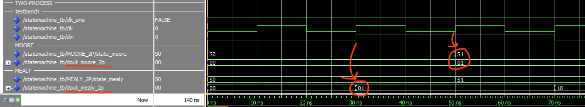
Fig. 2.56 Simulation result of a Moore and Mealy machine implemented using one synchronous process to update the current state and one combinational ouput process. Notice how the ouputs of the Mealy machine changes when the input changes and is one clock cycle in advance of the Moore machine.#
Compared to the one process implementation it is worth noticing that the output of the two process implementation changes immediately as a function of the input. The output logic is now implemented in a combinational process and any change on the process’ input signals will reflect immediately on the output. This is not the case for the one process implementation where output logic changes synchronously to the clock. Still for both the one process and two process implementation, the outputs of the Mealy machine changes one clock cycle in advance of the Moore machine.
2.13.7. Three process state machine#
For the three process implementation we need to declare two signals of the enumerated type.
These two signals will be used by the combinatorial input process to determine the next_state value that will be used to update the current_state on the next active clock edge.
Three process Moore
architecture moore_threeprocess of statemachine is

  type state_type is (S0, S1, S2);
  signal current_state_moore : state_type;
  signal next_state_moore    : state_type;

begin

p_comb_in : process(current_state_moore, din) is
begin
  case current_state_moore is
    when S0 =>
      if din = '1' then
        next_state_moore <= S1;
      else
        next_state_moore <= S0;
      end if;
    when S1 =>
      if din = '0' then
        next_state_moore <= S2;
      else
        next_state_moore <= S1;
      end if;
    when S2 =>
      if din = '1' then
        next_state_moore <= S0;
      else
        next_state_moore <= S2;
      end if;
  end case;
end process;

p_state : process(clk) is
begin
  if rising_edge(clk) then
    current_state_moore <= next_state_moore;
  end if;
end process;

p_comb_out : process(current_state_moore) is
begin
  case current_state_moore is
    when S0 =>
      dout <= "00";
    when S1 =>
      dout <= "01";
    when S2 =>
      dout <= "10";
  end case;
end process;


end architecture;
Three process Mealy
architecture mealy_threeprocess of statemachine is

  type state_type is (S0, S1, S2);
  signal current_state_mealy : state_type;
  signal next_state_mealy    : state_type;


begin

p_comb_in : process(current_state_mealy, din) is
begin
  case current_state_mealy is
    when S0 =>
      if din = '1' then
        next_state_mealy <= S1;
      else
        next_state_mealy <= S0;
      end if;
    when S1 =>
      if din = '0' then
        next_state_mealy <= S2;
      else
        next_state_mealy <= S1;
      end if;
    when S2 =>
      if din = '1' then
        next_state_mealy <= S0;
      else
        next_state_mealy <= S2;
      end if;
  end case;
end process;

p_state : process(clk) is
begin
  if rising_edge(clk) then
    current_state_mealy <= next_state_mealy;
  end if;
end process;

p_comb_out : process(current_state_mealy, din) is
begin
  case current_state_mealy is
    when S0 =>
      if din = '1' then
        dout <= "01";
      else
        dout <= "00";
      end if;
    when S1 =>
      if din = '0' then
        dout <= "10";
      else
        dout <= "01";
      end if;
    when S2 =>
      if din = '1' then
        dout <= "00";
      else
        dout <= "10";
      end if;
  end case;
end process;


end architecture;
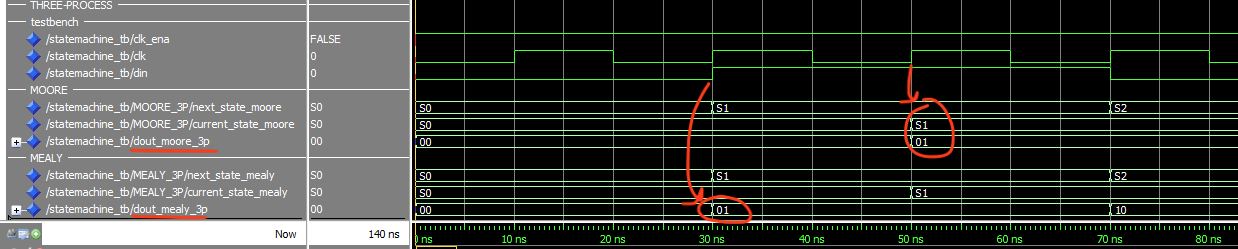
Fig. 2.57 Simulation result of a Moore and Mealy machine implemented using one synchronous process to update the current state, one combinational input process, and one combinational ouput process. Notice how the ouputs of the Mealy machine changes when the input changes and is one clock cycle in advance of the Moore machine.#
Final remarks
There is no right or wrong choice when deciding on a choice of implementation, both regarding the number of processes to use or whether to use a Moore or Mealy type behaviour. In practice you may implement a state machine that combines a Moore and Mealy behaviour. Some prefer to write the state machine using a single process only as this helps to reduced the risk of unwanted latches and ensures that all outputs are registered. While others prefer to split the state machine into a clocked process to update the state registers and separate combinational processes for the inputs and outputs. During a learning process, this approach may help to better identify what is combintional logic and what is synchronous logic.
The VHDL code for the examples including a simulation setup can be found here.
2.13.8. Supporting videos#
The following video gives and introduction to state machines in VHDL.
There are different approaches to describing state machines in VHDL. The following videos demonstrates how to describe state machines using a 1-process, 2-process, or 3-process approach. The examples also demonstrates the use of configurations in VHDL.
1-process state machine
The following video demonstrates how to write a 1-process state machine in VHDL.
The following video demonstrates the simulation of a 1-process state machine.
2-process state machine
The following video demonstrates how to write a 2-process state machine in VHDL.
The following video demonstrates the simulation of a 2-process state machine.
3-process state machine
The following video demonstrates how to write and simulation a 3-process state machine in VHDL.
You will find the code use in these examples under the organisation FYS4220 on Github: fys4220/fys4220-example-basic-statemachine