EX4: State machine#
In this exercise you will design state machine to control the transmission of data for the UART transceiver that you need for the embedded system project in this course.
The learning outcome of this problem is to:
To be able to describe and simulate a simple finite state machine in VHDL.
To be able to run simulations in Modelsim using scripting commands.
The state machine itself is rather simple with only two states as shown in the state diagram in Fig. 27. The state machine is activated on a high level of the signal tx_data_valid and changes to the sTRANSMIST state. In this state the state machine signals that the system is busy and waits for a high level on the signal tx_complete, which indicates that the transmission has completed, and that the state machine can return to the sIDLE state. The two control signals tx_data_valid and tx_complete are controlled by other modules that will be introduced later. Reset is asynchronous and active low; a and _n in areset_n.
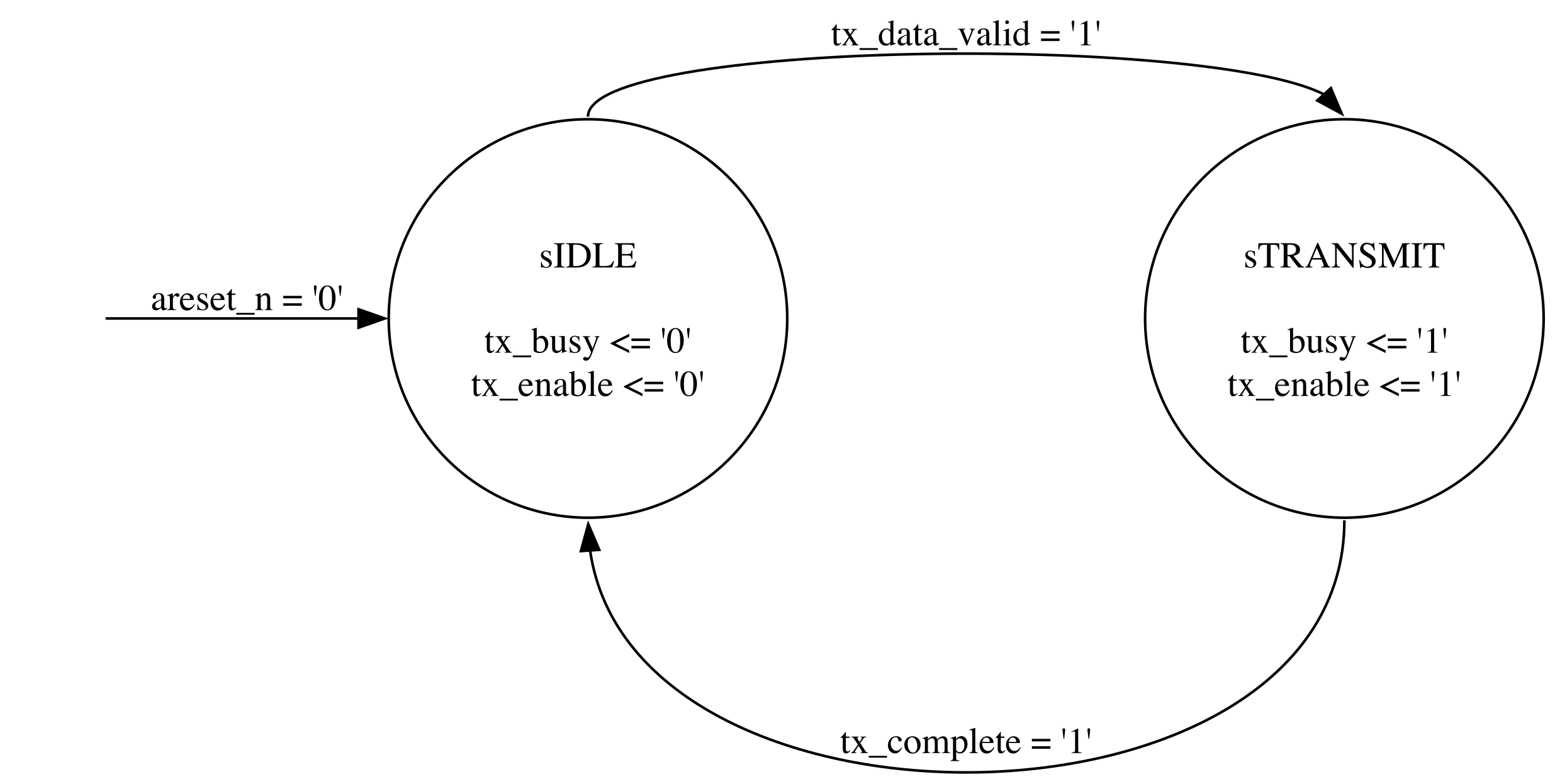
Fig. 27 State diagram for the TX UART FSM.#
Design the state machine and verify the correct behaviour through simulation in Modelsim. This exercise will not be tested in hardware.
The suggested top level entity connections are listed in Table 1. You are free to choose your own names for entities and signals, but it will be easier to follow the description and use any provided code or scripts if you follow the suggested names.
Name |
Direction |
Type |
|---|---|---|
clk |
in |
std_logic |
areset_n |
in |
std_logic |
tx_data_valid |
in |
std_logic |
tx_complete |
in |
std_logic |
tx_enable |
out |
std_logic |
tx_busy |
out |
std_logic |
When setting up the test conditions in the test bench, the inputs tx_data_valid and tx_complete signals shall be assumed to be synchronous to the clock and have a duration of one single clock cycle. Creating a single clock cycle pulse which is synchronous to the clock can be achieved with the following statements.
wait until rising_edge(clk);
tx_data_valid <= '1';
wait until rising_edge(clk);
tx_data_valid <= '0';
Fig. 28 shows an example behaviour of the input test signals.
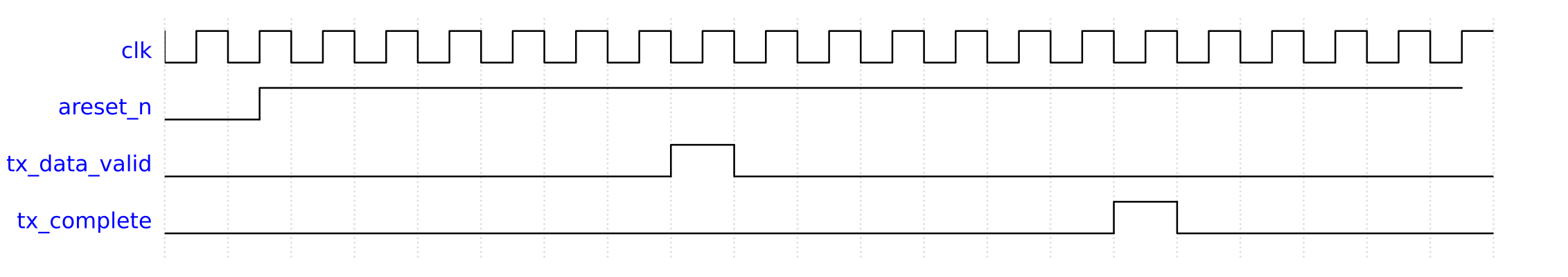
Fig. 28 Test signals for the state machine.#
Script based simulation#
Until now, you have run your simulations from Modelsim in a manual fashion, using mouse to perform relevant actions such as compile the code, start the simulation, add signals to the wave diagram. This works fine, but in the long run and for more complex designs, it is highly recommended to use a command and script based approach where the relevant commands can be typed and run directly in Modelsim’s Transcript window, or collected and grouped in one or several script files. The simulation can then be automated by simply calling the script file from the Transcript window.
The most relevant commands to learn are listed and explained below:
# The vlib command creates the work library into which all your code
# will be compiled. This is also creates a folder with the
# same name inside the directory where you run the command
vlib work
# The vmap command maps the logical work library with the
# folder of the same name in your file system
vmap work work
# The vcom command compiles your code. Add the -2008
# argument to compile using VHDL-2008. Provide the
# path to the file you want to compile relative to the
# folder from which you run the command
# Remember that the files need to be compiled in the
# correct order.
vcom -2008 ../src/tx_fsm.vhd
vcom -2008 ../tb/tx_fsm_tb.vhd
# To start the simulation you use the command vsim.
# The argument to the command is the design entity you
# want to simulation. This is usually the testbench
vsim tx_fsm_tb
# Open wave window
view wave
# Delete all waves
delete wave *
# add waves and dividers. The label argument
# is optional. If not applied, the full path of the
# signal will be use.
add wave -divider TX_FSM_TB
add wave -label clk /tx_fsm_tb/clk
add wave -label areset_n /tx_fsm_tb/areset_n

# To access signals in submodules, use the
# label name given when instantiating the modules,
# e.g., dut.
add wave -divider TX_FSM
add wave -label tx_data_valid /tx_fsm_tb/dut/tx_data_valid
add wave -label tx_complete /tx_fsm_tb/dut/tx_complete
add wave -label tx_enable /tx_fsm_tb/dut/tx_enable
add wave -label tx_busy /tx_fsm_tb/dut/tx_busy
add wave -label state /tx_fsm_tb/dut/state
# Run the complete simulation
run -all
# Restart the simulation reloading any changes after a recompilation of the code
restart
# A pop-up window will open and ask you to confirm to keep all settings.
# To automatically accept add the flag -f
restart -f
I recommend to split the commands into separate files depending on their function. This allows you to easily rerun only the relevant part during development and debugging. E.g., to avoid quitting and restarting the simulation when you change your design, your only rerun the commands that will recompile your code. A suggested setup is shown below:
Add commands related to compilation in a file called compile.do.
# Filename: compile.do
vlib work
vmap work work
vcom -2008 ../src/tx_fsm.vhd
vcom -2008 ../tb/tx_fsm_tb.vhd
Add commands related to populating the wave diagram in a file called wave.do.
view wave
delete wave *

add wave -divider TX_FSM_TB
add wave -label clk /tx_fsm_tb/clk
add wave -label areset_n /tx_fsm_tb/areset_n

add wave -divider TX_FSM
add wave -label tx_data_valid /tx_fsm_tb/dut/tx_data_valid
add wave -label tx_complete /tx_fsm_tb/dut/tx_complete
add wave -label tx_enable /tx_fsm_tb/dut/tx_enable
add wave -label tx_busy /tx_fsm_tb/dut/tx_busy
add wave -label state /tx_fsm_tb/dut/state
You can run the script files in the Modelsim Transcript window by writin do and then the filename, e.g.,:
do compile.do
Create a file than automates the full process.
do compile.do
vsim tx_fsm_tb
do wave.do
run -all
You can now run the individual files depending on the need. A typical scenario would be that you have made a small change to your code and want to recompile and rerun the simulation. You would then like to avoid calling the vsim command which makes a full reinitialization and restart of your simulation – with all the mad blinking of Modelsim windows!
Instead, call the compile.do script and restart the simulation with the restart -f command.
do compile.do
restart -f
run -all
You can combine commands by separating them with a semicolon.@
do compile.do ; restart -f ; run -all
I would also recommend to organize the various files in different folders according to their function as shown in Fig. 29. E.g., simulation script files in the sim folder, HDL design files in src and HDL test bench files in tb.
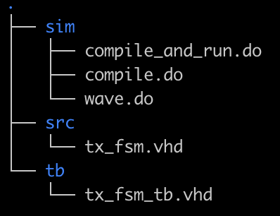
Fig. 29 A suggested folder structure.#