EX1: Your first FPGA project#
The most simple FPGA design that can be made is to make a connection between two pins of the FPGA, where we configure one pin an input and the other pin as an output. In this exercise you will use the 10 slide switches on the DE10-Lite board to control (turn on and off) the red Light Emitting Diodes (LED). The slide switches and LEDs can be seen in Fig. 17. Both the LEDs and the slide switches are physically connected to pins on the FPGA. Your task will be to create a VHDL design that connects these ports together. This will include:
Writing the VHDL statement that describes this connection.
Create a project in the Quartus design tools.
Setup the correct pinning assignments.
Synthesise the project and program the FPGA.
Verify that the design works by changing the position of the slide switches and observing the LEDs.
The learning outcome of this exercise is to:
Get familiar with the Quartus Prime design tool and the DE10-Lite board.
Be able to write and synthesize your first basic VHDL design.
And program the FPGA.
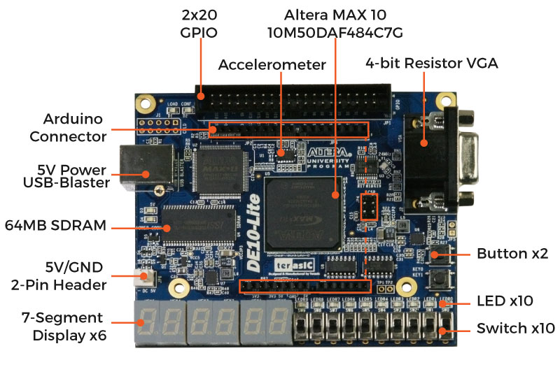
Fig. 17 DE10-Lite board.#
Prepare a new Git branch for the development of exercise 1.#
Clone your git repository to the local disk and create a new branch called ex1.
git clone https://github.uio.no/FYS4220-2023/<name of your git repository>
git branch ex1
Check that you have created the new branch by running the command git branch:
$ git branch
  ex1
* main
This command lists the available branches. The branch marked with a star is the active branch. The new branch can be activated by running the command git checkout command.
$ git checkout ex1
$ git branch
* ex1
  main
The branch ex1 is now marked with a star, which indicates that this branch is the active branch.
Supporting video#
In the following video I work through the exercise below. Note that the video is a few years old – some details like file and folder names will therefore be different. You should follow the naming convention as specified in the description on this page.
Create the Quartus Prime Project#
To start you first need to create a project in the Quartus Prime development tool. Creating a project in Quartus will generate a number of related project files. I therefore recommended that you organize your files in a dedicated directory for each exercise.
Create a new directory called e.g., ex1 in your local Git repository directory
Start the Quartus Prime program.
Create a new Quartus project (from File -> New Project Wizard) using the following settings:
Project directory: ex1
Project name: ex1
Name of top-level design entity: ex1
Project Type: Empty project
Device Family: MAX 10
Device name: 10M50DAF484C7G
Add files: Do not add any files at this stage
Under EDA Tool settings choose: No changes – use default settings.
For more information on the meaning of the device name see page 5 in Intel MAX10 FPGA device overview: https://www.intel.com/content/dam/www/programmable/us/en/pdfs/literature/hb/max-10/m10_overview.pdf
Write your first VHDL design#
The overall structure of the most typical VHDL-file can be divided in three parts as introduced in the section Design units and structure. You will now create a VHDL file and write the respective description for these three parts.
Create a new directory called src inside your ex1 directory
Open your favourite text editor (e.g. Notepad++ or VS Code) and create a file called ex1.vhd in the src directory. Remember to save the file in order to activate syntax highlighting.
Add the new VHDL file to the project. (Project -> Add/Remove Files in Project). Locate the file, press Add and then press OK.
Add the following template VHDL desciption to ex1.vhd.
library IEEE;
use IEEE.std_logic_1164.all;

-- The entity describes the interface
-- between the outside and the internal
-- functionality.
entity ex1 is
  port (
      -- sw is a 10-bit wide input port
      sw: in std_logic_vector(9 downto 0);
      -- led is a 10-bit wide output port
      led: out std_logic_vector(9 downto 0)
      );
    end entity ex1;

-- The architecture describes the internal functionality
architecture rtl of ex1 is

begin

  -- The following statement will connect the input signal vector _sw_ to
  -- the output signal vector _led_
  led <= sw;

end architecture rtl;
Tip
When you have multiple signals or ports of the same name these can be bundled together using the std_logic_vector type. The std_logic is the most commonly used type in VHDL, and the std_logic_vector is the array version of it.
You can read more about std_logic and std_logic_vector in the section Data types.
Commit and push the new file#
It is generally recommended to regularly commit your work to keep track of your development. This allows you to easily roll back to previous working version of your code. To exercise this, you will now add the new file under version control and push it online to your Github repository.
git add ex1.vhd
git commit -m "created the new file ex1.vhd"
git push origin ex1
Go online and verify that the new file is visible under the ex1 branch of your repository. You can change which branch is visible by using the dropdown button to the top left above your listed files as shown in the figure below.
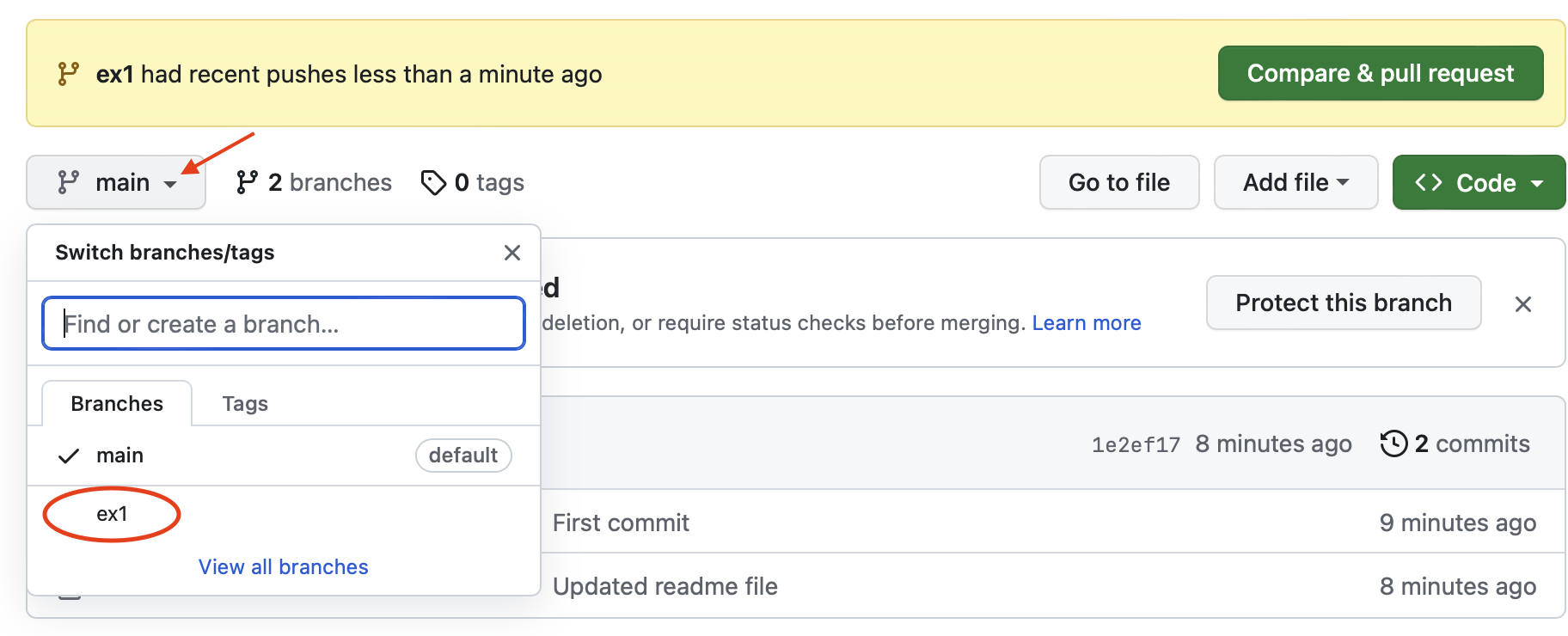
Fig. 18 The dropdown menu shows the to available branches.#
Pinning assignment#
The slides switches and the LEDs are hardwired to specific FPGA pins. It is therefore necessary to inform Quartus about which pins to use, that is, the “address” of the relevant pins.
The correct pin assignments can be found in the DE10-Lite User Manual which can be download from Terasic. For example, the manual specifies that sw[0] is connected to the FPGA PIN C10 and led[0] is connected to PIN A8. Each pin can be assigned manually through the Quartus Prime pin assignment manager, however, a more elegant and time saving approach is to make the pin assignment using a Tcl scripting file.
Create a new file called de10-lite-pinning.tcl in your ex1 directory.
Open the new Tcl-file in your favourite text editor and enter the required pinning constraints as show below.
#Toggle switches
set_location_assignment PIN_C10 -to sw[0]
set_location_assignment PIN_C11 -to sw[1]
set_location_assignment PIN_D12 -to sw[2]
set_location_assignment PIN_C12 -to sw[3]
set_location_assignment PIN_A12 -to sw[4]
set_location_assignment PIN_B12 -to sw[5]
set_location_assignment PIN_A13 -to sw[6]
set_location_assignment PIN_A14 -to sw[7]
set_location_assignment PIN_B14 -to sw[8]
set_location_assignment PIN_F15 -to sw[9]

#LED outputs
set_location_assignment PIN_A8 -to led[0]
set_location_assignment PIN_A9 -to  led[1]
set_location_assignment PIN_A10 -to led[2]
set_location_assignment PIN_B10 -to led[3]
set_location_assignment PIN_D13 -to led[4]
set_location_assignment PIN_C13 -to led[5]
set_location_assignment PIN_E14 -to led[6]
set_location_assignment PIN_D14 -to led[7]
set_location_assignment PIN_A11 -to led[8]
set_location_assignment PIN_B11 -to led[9]

#To avoid that the FPGA is driving an unintended value on pins that are not in use:
set_global_assignment -name RESERVE_ALL_UNUSED_PINS_WEAK_PULLUP "AS INPUT TRI-STATED"
Add the new Tcl-file to the project (Project -> Add/Remove Files in Project). The Tcl-file may not be visible by default. Change file file filter to All Files (*.*).
Run the tcl script to activate the pin assignments (Tools -> Tcl Scripts). The Tcl-script should be visible under the project folder. Mark the file and click RUN. Verify that the correct assignments have been performed by opening the pin assignment editor (Assignments -> Assignment editor). You should see a similar list as shown in figure ref{fig:assignment_editor}.
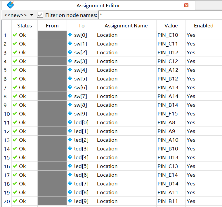
Fig. 19 The Quartus assignment editor lists all connections between entity port names and physical pins of the FPGA as a result of running the DE10-lite-pinning.tcl script.#
Tip
When the Tcl file is added to the project, you can also (re)run the script from the Tcl Console Window using the command source DE10-lite-pinning.tcl. The Tcl Console Window can be opened from (View –> Utility Windows) or through the short-cut Alt+2. Make sure you are in the same directory as the source file. You can check the current director using the command pwd. Change directory using the command cd .. to go up one level, or cd
Warning
It is important that the entity port names match the names used in the Tcl set_location_assignment statement. If not, the ports of the VHDL entity description will not be connected to the corret physical pin of the FPGA.
If the entity port names are not associated to specific pins, Quartus will still have to connect the ports to pins when the design is synthesized. This will result in random connections. As a result, the slides swithces will not be connected to the LEDs.
Whenever you make changes to the pinning file or include it in a new project, you will ned to (re-)run the Tcl-script.
Compile the project#
Compile the project: (Processing -> Start Compilation)
During compilation of the project you will see some warning and critical warning messages related to missing constraint information, e.g. :
Some pins have incomplete I/O assignments.
No clocks defined in design.
Synopsys Design Constraints File file not found.
These warnings can for the moment be ignored. If the compilation of the project was successful, Quartus has generated and SRAM object file (.sof), either in the project directory itself or in the directory output-files under the project directory. This is the programming file that will be downloaded to the FPGA.
Program the FPGA:#
Make sure to connect the USB cable to the USB connector on the DE10-Lite.
Open the Quartus programmer (Tools -> Programmer).
If the field next to the button ”Hardware Setup” shows ”No Hardware”, make sure the USB cable is connect to both the PC and the DE10-Lite board, and that the power is turned on. Press the ”Hardware Setup and choose ”USB-Blaster [USB-0]” under the ”Currently selected hardware”. Press Close.
Note!
USB-Blaster driver installation on Windows:
If you have connected DE10-Lite board to you computer, and the USB-blaster does not show up in the Quartus programmer tool, you might need to install the driver.
If you do not see an entry in the File filed, press auto detect to automatically detect the FPGA device. If you are asked to choose a specific device, choose the 10M50DA.
Double click on the File field of the listed device and select the correct programming file (.sof extension). Tick the box for ”Programming/Configure”.
To program the FPGA press Start.
Verify that your design works by changing the position of the toggle switches on the DE10-Lite board.
Remember to update your assignment progress status in the readme.md file before updating the Git repository.
Question to consider!
What value is required on the ouputs to turn on the LEDs? Can you explain why?
With value we here mean whether you have to set it to a high voltage or low voltage. That is, assign the value ‘1’ or ‘0’.
Update the git repository:#
When you have completed this exercise make sure to save your changes and push them to the git repository:
git add -A
git commit -am "First FPGA project completed"
git push origin ex1
To check which files have been added to the git repository write the command
git ls-files
You should see a similar result:
.gitignore
readme.md
ex1/de10-lite-pinning.tcl
ex1/src/ex1.vhd
ex1/ex1.qpf
ex1/ex1.qsf
Create a pull request to complete the exercise#
You have now created and programmed your first FPGA design and are ready to merge your solution into the main branch using a pull request. Press the Compare & pull request button, write a descriptive text briefly explaining what you have done. If you want your solution reviewed by the course instructor, add the user ketilroe as both reviewer and assignee, then finally press the Create pull request button. If you are content with your solution and don’t need it reviewed, create the pull request and complete by merging the pull request yourself.