EX7: Nios II interrupt handling#
In this exercise you will add interrupt handling to the microcontroller system.
The learning outcome of this problem is to:
Be able to configure the PIO modules as an interrupt source.
Be able to write software routines to handle the interrupt.
To demonstrate interrupt handing in the Nios II system we will use one of the two push buttons on the DE10-Lite board as the interrupt source. KEY0 is already in use for the asynchronous active low reset. For this example we will therfore use KEY1, which is connected to PIN_A7 of the MAX10 FPGA. To implement the interrupt functionality we need to add new hardware and software. The required software API was already introduced above, while the hardware can be implemented with the appropriate configuration of a PIO core.
Fig. 41 shows an overriew of the system. For completness, this figure now also includes the clock source component that is required by the system to connect and distribute the system clock and reset signal to system modules.
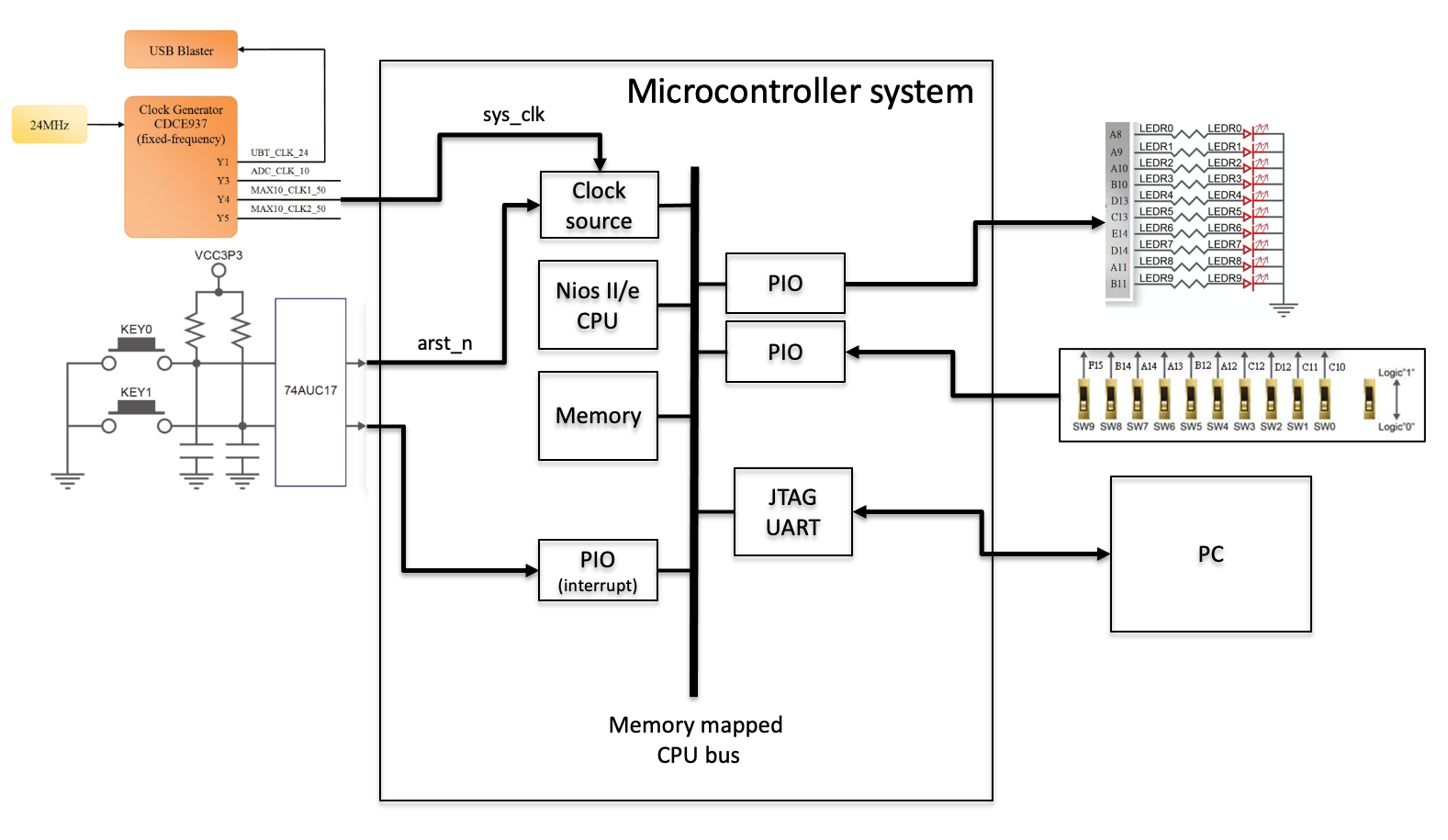
Fig. 40 An overview of the system with the PIO module that will be configured to handle an interrupt event from an external push button.#
A PIO core has a memory mapped register space with four main registers: data, direction, interruptmask, and edgecapture, as seen in Fig. 41. The additonal registers, outset and outclear, are implemented if the option Enable individual bit set/clear output register is enabled.
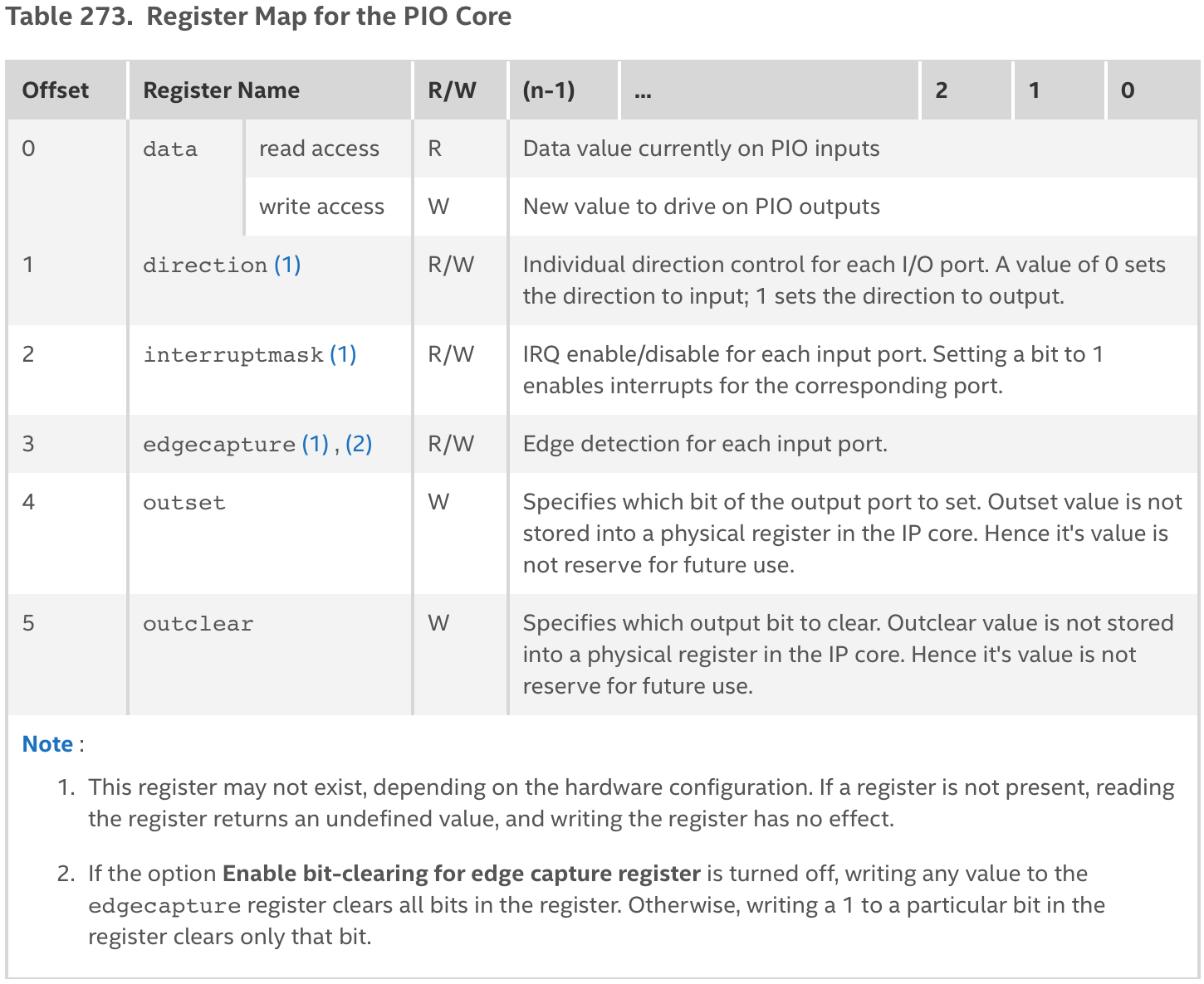
Fig. 41 Register map for the PIO module. Table 273 on page 311 in the Intel Embedded Peripherals IP User Guide.#
The PIO core is configured when it is added to the Nios II system in the Platform designer. For this example we want to turn on synchronously capture to include the edge capture register in the core. This register allows the core to detect and generate an interrupt when an edge of the specified type (falling or rising) occurs on an input port. We must therefore also specify the type of edge detect to be falling edge, and turn on Generate IRQ to assert an IRQ output. For the IRQ event, we must also specify that this should happen on the Edge of the input event. The core will then generate an IRQ whenever a specific bit in the edge capture register is high and interrupts are enabled for that bit in the interruptmask register. The configuration of the PIO core is show in Fig. 42.
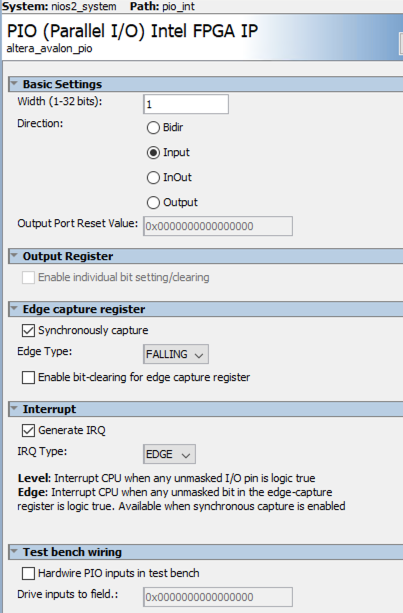
Fig. 42 Configure PIO core as a 1-bit input with synchronous capture of interrupt on falling edge.#
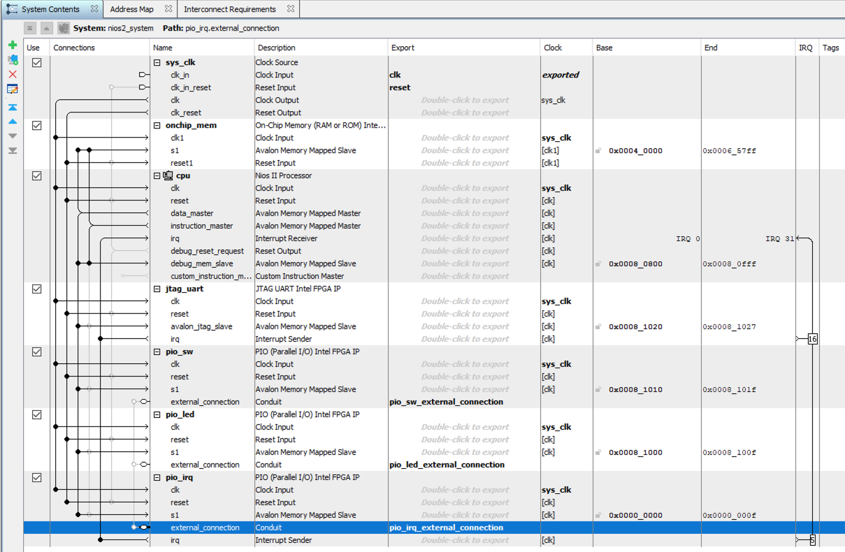
Fig. 43 Nios II system with added PIO core for handling an interrupt.#
And the final system should now look similar to Fig. 43. Make sure to regenerate the system.
Updating top level HDL and pinning#
Since we have added a new PIO core configured as an input, we also need to update the top level VHDL description.
library ieee;
use ieee.std_logic_1164.all;

entity system_top is
  port (
    clk : in std_logic;
    arst_n : in std_logic;
    led : out std_logic_vector(9 downto 0);
    sw : in std_logic_vector(9 downto 0);
    irq : in std_logic -- KEY1
  );
end entity;

architecture rtl of system_top is

  component nios2_system is
    port (
      clk_clk : in std_logic := 'X'; -- clk
      reset_reset_n : in std_logic := 'X'; -- reset_n
      pio_sw_external_connection_export : in std_logic_vector(9 downto 0) := (others => 'X'); -- export
      pio_led_external_connection_export : out std_logic_vector(9 downto 0) := (others => 'X'); -- export
      pio_irq_external_connection_export : in std_logic
    );
  end component nios2_system;

  -- To bit register for synchronization
  signal irq_sync : std_logic_vector(1 downto 0);

begin

  -- The irq input signal is a button press which is asynchronous to the system clock
  -- The irq input must therefore be synchronized
  p_sync: process(clk)
  begin
    if rising_edge(clk) then
      irq_sync <= irq_sync(0) & irq; --synchronization shift register
    end if;
  end process;

  u0 : component nios2_system
    port map(
      clk_clk => clk, --   clk.clk
      reset_reset_n => arst_n, -- reset.reset_n
      pio_sw_external_connection_export => sw,
      pio_led_external_connection_export => led,
      pio_irq_external_connection_export => irq_sync(1)
    );

  end architecture;
Remember to also add the required pin assignment for the newly added interrupt input and rerun the Tcl pinning script.
# key1 - used as interrupt
set_location_assignment PIN_A7 -to irq
Recompile the Quartus project to create a new programming file.
Update the software application#
To handle the interrupt in software we need to use the API introduced in Section 3.6.1. This included writing an interrupt service routine to handle the interrupt, and then to register this ISR in the system.
The flow of the interrupt execution is a follows:
The button is pressed, generating an IRQ from hardware
The ISR gains control:
The processor branches to the address in the vector table, which transfers control to the ISR (handle_interrupts())
handle_interrupts() services the hardware interrupt, stores relevant information about the interrupt (edge_caputure) and returns.
Normal program operation continues with an updated value of edge_capture variable
When writing an interrupt service routine you want to minimize the impact running the ISR will have on the system. Interrupts are by nature asynchronous and non-deterministic, and adding application code to the ISR will therefore increase the execution jitter of the system. When used in a real-time operating system, this will make the system less predicitable and increase the chance of not meeting deadlines.
The code example below demonstrates interrupt handling in a Nios II system.
#include <stdio.h>
#include "system.h" //access Nios II system info
#include "io.h" //access to IORD and IORW
#include "unistd.h" //access to usleep
#include "altera_avalon_pio_regs.h" //access to PIO macros
#include <sys/alt_irq.h> // access to the IRQ routines

/* Declare a global variable to holds the edge capture value
Declaring a variable as volatile tells the compiler that
the value of the variable may change at any time without
any action being taken by the code the compiler finds nearby.
This variable will be connected to the interrupt register which
is controlled from HW and not SW. The compile will therefor not
find any code that controls this variable, and if not declared as
volatile, the compile may decided to optimize and remove this variable. */
volatile int edge_capture;

/* This is the ISR which will be called when the system signals an interrupt. */
static void handle_interrupts(void* context)
{
    //Cast context to edge_capture's type
    //Volatile to avoid compiler optimization
    //this will point to the edge_capture variable.
    volatile int* edge_capture_ptr = (volatile int*) context;

    //Read the edge capture register on the PIO and store the value
    //The value will be stored in the edge_capture variable and accessible
    //from other parts of the code.
    *edge_capture_ptr = IORD_ALTERA_AVALON_PIO_EDGE_CAP(PIO_IRQ_BASE);

    //Write to edge capture register to reset it
    IOWR_ALTERA_AVALON_PIO_EDGE_CAP(PIO_IRQ_BASE,0);

}

/* This function is used to initializes and registers the interrupt handler. */
static void init_interrupt_pio()
{
    //Recast the edge_capture point to match the
    //alt_irq_register() function prototypo
    void* edge_capture_ptr = (void*)&edge_capture;

    //Enable a single interrupt input by writing a one to the corresponding interruptmask bit locations
    IOWR_ALTERA_AVALON_PIO_IRQ_MASK(PIO_IRQ_BASE,0x1);

    //Reset the edge capture register
    IOWR_ALTERA_AVALON_PIO_EDGE_CAP(PIO_IRQ_BASE,0);

    //Register the interrupt handler in the system
    //The ID and PIO_IRQ number is available from the system.h file.
    alt_ic_isr_register(PIO_IRQ_IRQ_INTERRUPT_CONTROLLER_ID,
        PIO_IRQ_IRQ, handle_interrupts, edge_capture_ptr, 0x0);

    /* In order to keep the impact of interrupts on the execution of the main program to a minimum,
    it is important to keep interrupt routines short. If additional processing is necessary for a
    particular interrupt, it is better to do this outside of the ISR. E.g., checking the value
    of the edge_capture variable.*/

}


int main(){
    printf("Hello, World!\n");
    int sw_data = 1;

    // Initialize the interrupt
    init_interrupt_pio();

    while(1){
        //Access registers using IORD and IOWR from io.h
        sw_data = IORD(PIO_SW_BASE,0);
        IOWR(PIO_LED_BASE,0,sw_data);

        //Alternative solution using PIO macros
        //sw_data = IORD_ALTERA_AVALON_PIO_DATA(PIO_SW_BASE);
        //IOWR_ALTERA_AVALON_PIO_DATA(PIO_LED_BASE,sw_data);

        // When an interrupt event has occurred, the edge_capture variable has been updated
        // Poll the edge capture variable check for interrupt
        if (edge_capture == 0x1) //bit position 0 corresponds to button press
        {
            printf("Interrupt detected, Key1 was pressed!\n");
            edge_capture = 0; // reset variable to "unregister" event
        }

        usleep(100000); //sleep 100 us

    }
    return 0;
}
Update the software application app.c. Since the hardware of the Nios II system also has been updated, we must also regenerate the board support package. Navigate to the software folder and type:
$ nios2-bsp hal app_bsp ../quartus/nios2_system.sopcinfo
Recompile the software application
Navigate to the software folder and type:
make
Reprogram the FPGA, download the new software application, and start the *nios2-terminal.exe” application. Press the push button KEY1. The expected result should look like this:
$ nios2-terminal.exe
nios2-terminal: connected to hardware target using JTAG UART on cable
nios2-terminal: "USB-Blaster [USB-0]", device 1, instance 0
nios2-terminal: (Use the IDE stop button or Ctrl-C to terminate)

Hello, World!
Interrupt detected, Key1 was pressed!
Example code on Github
The code for this example can be found here: fys4220/fys4220_nios2_example